ARM - Assistive Reach Mechanism
Abstract
Our goal is to create a mechanical prosthetic which aids with reaching and grabbing; the device is targeted for persons with limited reach or mobility.
Team members
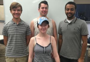
Abigail Sawyer, Josh Watkins, Mohammad Aljohar, Dakota Bell
Problem Statement/overview of the need
The problem concept is to create a generalized prototype that can be adapted to suit individual people. The idea is to create a device that will extend the natural reach of the user and allow them to lift and manipulate objects that they would otherwise be unable to reach. The original concept assumes normal grip strength and hand mobility. The device should be easy, safe, and comfortable to use, as well as aesthetically pleasing.
Design Specifications
1. Extend Reach The device must extend reach by at least one foot.
2. Practical The extended reach must have a mechanism which can open cabinet doors; pick up, hold, and carry cans of 4 lbs; and pick up plates.
3. Ergonomic The device must be adjustable and safe.
Background research
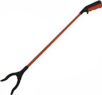
There is already a market for "reaching devices" that can be used to grab or pick up things that are out of reach; most of these devices, however, are cumbersome to carry around or are built very cheaply. These devices have three main issues that we wanted to address.
1. Commercially available extended grippers typically cannot hold heavy items without some slip occurring between the claw and the object the individual is trying to pick up.
2. The gripping mechanism is typically held in the hand with no additional attachments for stability. When picking up objects over a certain weight, it is difficult for the user to hold the item up.
3. The claw on most gripping mechanisms currently available has a small surface area and is thin, which severely limits the items an individual can manipulate.
Conceptual Design
Arm Designs
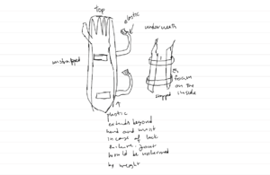
Fixed Arm
- This design would be very similar to what is on the market today. The arm would be one solid piece with no joints or telescoping mechanisms.
- The arm would be strapped onto the forearm of the user
- Pros: Simple design, easy to build, lightweight, safe to use
- Cons: Limited versatility, not compact/hard to carry around
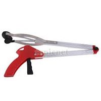
Folding Arm
- This design would feature a hinge in the middle of the arm that would allow it to fold up for easy transport.
- Has a locking mechanism to keep the arm extended while in use
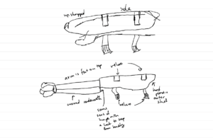
- Pros: Compact design, easy to fold/unfold, simple design, easy to build
- Cons: Could be unsafe if locking mechanism fails, design inherently limits maximum reach
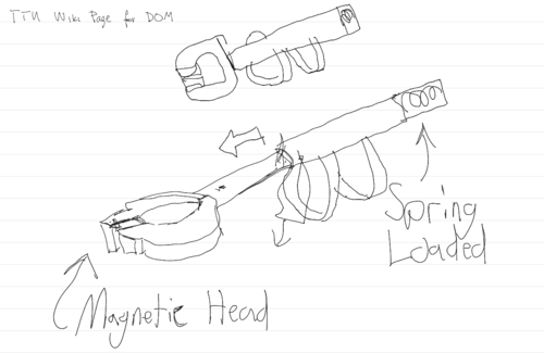
Telescopic Arm
- This design features a telescoping portion that is spring-loaded and can be extended upon command
- Pros: Compact design, easy to extend, potential for very long reach
- Cons: More complicated, possibly heavy, spring-mechanism could release accidentally
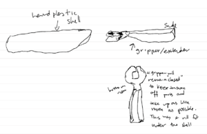
Gripper Designs
Claw
- Solid, two piece claw used to grab/pick up objects
- Rubber tips for improved grip
- Pros: Very simple design, very durable
- Cons: Small contact surface could make it hard to pick up oddly shaped or heavy objects
Gripper
- Features a claw with a flexible membrane stretched between the hinge and tip
- Membrane will deform to grab round/oddly shaped objects
- Pros: Large contact surface would make it easy to grab a variety of objects
- Cons: Rubber membranes could tear/wear out, heavier than simple claw
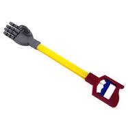
Hand
- This design calls for a humanoid hand that is used to pick up/manipulate objects
- Each finger could be actuated individually to perform more complicated facts
- Pros: Could manipulate objects and perform complicated tasks, would be able to hold almost any object
- Cons: Complicated design, difficult to build, inherently more fragile
Evaluate concepts/select candidate
| Arm Concepts | Fixed | Folding | Telescoping | Folding and Telescoping |
|---|---|---|---|---|
| Safety | 5 | 4 | 3 | 4 |
| Durability | 5 | 4 | 4 | 3 |
| Weight | 5 | 4 | 4 | 3 |
| Easy to Use | 2 | 5 | 4 | 5 |
| Easy to Build | 5 | 4 | 4 | 3 |
| Wearability | 3 | 5 | 5 | 5 |
| Reach Length | 3 | 3 | 5 | 5 |
| Total | 28 | 29 | 29 | 28 |
| Gripper Concepts | Claw | Gripper | Hand |
|---|---|---|---|
| Contact Surface | 2 | 5 | 4 |
| Durability | 5 | 4 | 2 |
| Easy to Build | 5 | 4 | 2 |
| Total | 12 | 13 | 9 |
Detailed Design
1. The design process began with the team deciding on the specific tasks ARM would complete.
2. Next, rough sketches of each of the suggested designs were put forward.
3. Each of the designs were then evaluated with the final design chosen based on its ability to complete the tasks the team chose to focus on (as the team did not receive a customer.) The team also sought input from the instructor.
4. From there, the team created CAD files to give full, visual models.
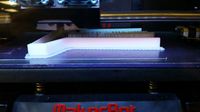
5. The CAD files were converted to .stl files and 3D printed.
6. During the fabrication process, minor adjustments were made as necessary (such as changing the location of where the sheathed cable would be attached to the handle the user grips.)
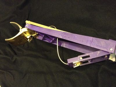
Description of selected design
The finalized design utilizes a folding portion as well as an articulating wrist. The forearm brace will be pinned to the support section of the device and then pinned again at the wrist.
Detailed description of selected design
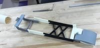
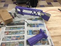
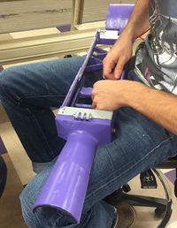
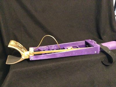
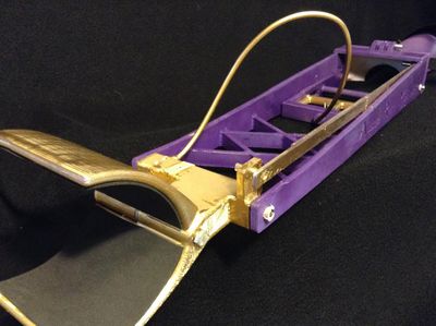
The final design is constructed mostly of 3-D printed ABS plastic, with some parts printed in PLA. The design folds at the end of the part fitted to the user's arm. Velcro straps attached to the top of the forearm brace can be fitted around the arm so that a variety of forearm sizes may be accommodated. The main tension beam, which is designed like a truss, reaches out from the shell covering the forearm. The articulating wrist is controlled by a parallel four bar linkage that transmits a 1:1 motion of the input to the claw, and is actuated via a sheathed cable running from the slider bar to the joint of the claw (to allow for closure.) The claw is a simple two-bar claw, but features a curved shape with foam for added grip. Along the inside of the forearm brace, foam has been added for safety and comfort. Foam was also added to the claw to increase grip ability as the plastic was slick.
Analysis
Engineering analysis 1
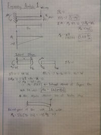
Analysis of the support arm shown as a simple Cantilever beam. Specific example was worked out with the arm holding a 5 lbs weight. Internal Stresses were calculated at the midpoint of the beam.
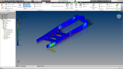
Engineering analysis 2
Below is an FEA carried out in Inventor on the main brace of the arm. The load is a 20 lbf horizontal point force assuming the back face is fixed. The max stress generated is around 35 MPa; the tensile strength of ABS plastic is around 7000 psi.
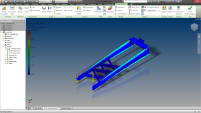
Engineering analysis 3
Below is another FEA showing a 40 lbf vertical load applied to the end of the main brace. The maximum stress generated is around 24 MPa
CAD Drawings
Insert drawings of all parts and the assembly
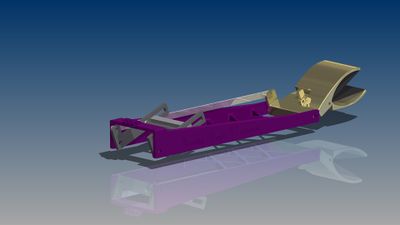
This is a complete assembly of the extension half of the arm.
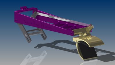
Same Assembly, Different view
Bill of Materials
| Material | Quantity | Price | Description | Link |
|---|---|---|---|---|
| ABS/PLA plastic | 1 | n/a | Plastic | n/a |
| Foam sheet | 2 | $0.33 each | 8.85" x 11.8", Item: 551176130 | [1] |
| Sleeved cable | 1 | $10 | Length, 48" | Provided by ME shop |
| Wooden dowel | 1 | $0.90 | 3/8" diameter | From Highland Hardware |
| Grade 5 hex bolt | 2 | n/a | 1/4" diameter | From Highland Hardware |
| Rubber band | 1 | tbf | n/a | n/a |
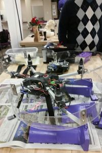
| Spray paint | 2 | n/a | Purple and gold | Provided by Maker Space |
| Gloss acrylic paint | 2 | $0.97 each | Gloss as opposed to matte to prevent flaking. Quick dry to allow multiple coats in a short time. | [2] |
| J-B Weld | 1 | $5 | J-B Weld product | From Highland Hardware |
| Super Glue | 1 | $3 | Super glue | Highland Hardware |
| Total | 14 | $21.50 |
Assembly Instructions
- Step 1: Initially, all items must be in .stl files to transfer to a 3D printer, where the parts will be printed.
- Step 2: The side pieces must be pieced together (like puzzle pieces.)
- Step 3: The device must be pinned at the joining of the forearm brace and extended section and again at the wrist joint. A sheathed cable must be attacked from the prismatic to the wrist joint to ensure claw closure. To keep the claw open, a rubber band (or a spring) must be added to the wrist area. It must directly influence the claw.
- Step 4: Paint the device.
- Step 5: Measure, cut, and super glue foam to the inside of the forearm brace where the user will come in contact with the device.
- Step 5: Measure, cut, and super glue foam (or rubber) to the inside of the claw.
- Step 6: Super glue Velcro to the top of the forearm brace to allow adjustable fitting of ARM.
Fabrication Process
Testing and implementation
Describe testing, delivery, how used/received by the family
- The product was tested by frequently opening and closing the claw and ensuring that all parts moved freely and as intended. A variety of objects were picked up, both large and small, including (but not limited to): water bottles, cups, mugs, erasers, spray paint cans, and irregularly shaped objects (such as 3D printed parts.)
- The finished product was not delivered to a family, however, it was evaluated by two individuals outside of the class, as well as the instructor.
Photos of Completed design
Instructions for safe use
Provide a clear summary of safe use for the family.
- 1. Do not use the device unless supervised by an adult that has been fully understood the safe use of this product.
- 2. Do not use the device if the foam padding in the inside cuff is coming off.
- 3. Do not exceed the maximum weight of 5 lbs.
- 4. Do not use this device to pick up hot items.
- 5. The device is intended for reaching and picking items up, do not use for actions other than this.
- 6. The device is intended to be worn on the top of the arm. It doesn't not matter which hand.
Project Summary, Reflection
Project Summary
Overall, the majority of the project utilized the 3D printers and Maker Space facilities. All four team members learned to manage their time and work within other's schedules. While the team did not receive a family to deliver the product to, it did not dampen the excitement of seeing a project come together. With the assistance of the Maker Space staff and the instructor, ARM was able to be designed and built, hopefully as a base design that can be improved for the benefit of others.
Reflection
The most exciting part of the project was seeing everything we had learned in class applied to a real life situation. The project was challenging not in its initial design, but as the project progressed, it was fun to see what challenges we would face. It was an excellent experience for the team to see what it was like to go through the design and fabrication process with a time frame and goal in mind. As future engineers, hands on experience like this is invaluable.