Adjustable Bed
Contents |
Abstract
A family had new addition of twins, but they were born prematurely at 30 weeks. As a result, they each have some respiratory issues which require them to be on breathing machines when sleeping. Both children are prone to choking while eating, and choking remains a very real risk for several hours after eating. This problem is drastically amplified when the twins are laid flat in bed. Some attempts have been made by the family to keep them propped up in their beds, but the parents would like something adjustable to keep the children elevated, comfortable, and in position when needed.
Team Members

Left to Right: Colten Dotson, Alex Williams, Blake Sims, Jacob Warren, Chris Smith
Special thanks to:
Heather Craig - Service Coordinator, TN Dept. of Education
Problem Statement/Overview of the Need
The parents of the twins requested that we design and construct two adjustable beds that are about the same size as the twins' existing bassinets that will allow the children to be comfortably elevated and properly digest their food without the risk of choking. It is evident that, for lack of better phrases, a bed is a bed, and an incline is an incline. It is easy to envision a bed that is elevated towards the head. Thus, the frame of the bed is not truly the issue we are tasked with. The big problem we are facing is how to adjust said incline across a range of desired angles, and doing so without compromising the rigidity, strength, and comfort of the bed. The product we deliver must be strong and dependable. Due to the nature of the health problems the twins are having, a device that has any potential for problems now or down the road is not option.
Design Specifications
Reliability:
There needs to be confidence that the child will stay inclined as intended. Any chance of failure must be eliminated. Due to the nature of the problem, malfunction of the bed would likely result in dire consequences.
Size:
The final product needs to approximately the same size as the twins existing beds. A normal bassinet is about 15" x 30". This compact size constraint will be a driving factor in the design of twins' beds.
Adjustability:
We want to have the option to have the bed go from horizontal to as inclined as the twins would need, with many options for incline in between. The family informed us that 30 degrees is the most common angle they will want to use. We decided that it would not be a bad idea to shoot for 45 degrees, so that they can be inclined more if needed. We also want the bed to be able to fold completely flat for ease of transportation.
Ease of operation:
Ideally, the motion of inclining the child would be a one handed operation so that the parents can adjust the bed while holding a child in the other arm. The handle for actuating the adjustment mechanism would be at the ends of the bed where it is most natural to grab for adjustment. However, accommodating smooth, one-handed operation introduces a great deal of complexity into the design. The more complicated this device becomes, the more opportunities that arise for malfunction. Due to safety precautions, it may be better to go with a simpler, more sure-fire adjustment mechanism that will never cause issues, even if this does create a slight hassle in adjustment.
Mobility/weight:
The bed should be mobile/light enough for one person to lift and transport easily. Lighter weight components will be easier to control when adjusting, moving, or transporting the bed.
Replicability:
Each child needs to have adjustment in their own bed. The design should be affordable and simple enough to produce 2 of the same thing in the given time frame in a manner that both beds are made the same quality. There should not be areas that are difficult to get correct when fabricating the bed, as this could lead to one bed being better, stronger, etc. in the end.
Background research
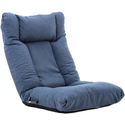
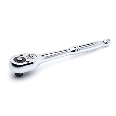
There are a few options on the market that could be applied to this problem. There are shaped foam toppers to lay in an provide and incline but offer no adjustability. There are chairs like the one shown below that are adjustable, but they are often too big for our application of fitting in each twin's bed. The inclining and reclining chairs also typically require the seat to be folded all the way in one direction in order adjust in the opposite direction, which is inconvenient to have to do repeatedly. We also looked into using ratchets as the pivot points for adjustment, but this idea was ruled out due to the complexity of reversing the ratcheting direction and the potential for that mechanism to malfunction.
Conceptual Design
Overall Concept
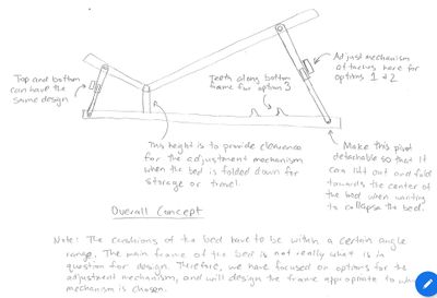
The overall bed frame will be very similar across all three conceptual designs. There will be a back/head rest portion as well as a leg/foot rest portion, both of which will be adjustable. We intend to use a thin sheet of plywood to top our frame, with standard eggshell material for padding. The placement of adjustment mechanisms and pivot points varies based on design concept. See more detailed descriptions below.
Design Concept 1 - Spring Loaded "Crutch Button"
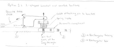
- This option functions similarly to the way crutches, canes, etc. are extended or contracted. It involves a "button" of sorts that slides through aligned holes in two separate pieces of material, preventing the two pieces from sliding relative to one another. This design, as well as the others, presents the challenge of how to actuate the mechanism from above the bed. (Reaching in from the side is not an option because the bed we construct will have to sit down in a bassinet that has closed sides.) We decided that one solution to this problem is making use of a mechanism modeled after bicycle brakes. As shown in the image above, the cable, attached to a handle towards the head of the bed, would pull on an L-shaped plate that rotates about a fixed pivot. This would cause one end to travel perpendicularly away from the support, pulling the button out of engagement between the two main pieces of the support. This allows the bottom piece of the support to slide within the top piece. When the handle is released, the spring behind the button would pop the button into the nearest hole in the support, locking the bed into position.
- In order to fold the entire bed flat for transportation and/or storage, you would disconnect the bottom of the support arm from the base of the frame and pivot the arm inwards, allowing it to tuck between the base of the bed and the back rest. Latches could be included to secure the bed in the collapsed position to allow a person to pick it up as one solid unit, and move it easily. This also applies to Design Concept 2.
- Important note: the pivot of the bed would have to be raised above the frame to ensure that we are able to collapse/extend the support arm enough to produce the desired angle range for the bed. From the picture shown in the "Overall Concept" section above, you can see that the support arm, when fully extended, can be at most twice as long as when it is fully contracted. This problem is a major limitation of both this design and Design Concept 2. One way to resolve this issue would be to make a telescopic support arm; however, doing so would introduce a great deal of unnecessary complexity into the design.
Design Concept 2 - Grabber Mechanism
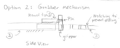
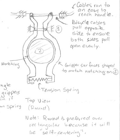
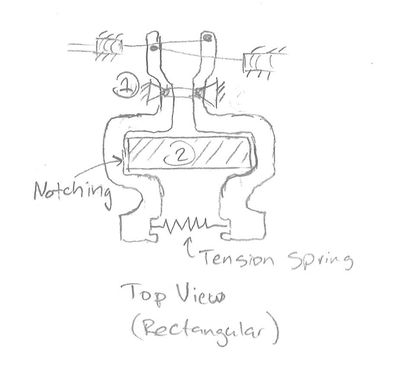
- This design is somewhat similar to design 1; however, this design would allow for much finer adjustment.
- This design would also involve a two piece support arm, with the lower part sliding inside the upper part. However, with this design, a “Grabber Mechanism” would be attached to the upper side, allowing it to hold on to the lower side to fix the overall length of the support arm. (See pictures)
- Operating this design would be the similar to design 1. There would be 2 bicycle cables pulling in opposite directions to open the ‘fingers’ of the grabber mechanism, which would be held closed by a spring when the handle is released.
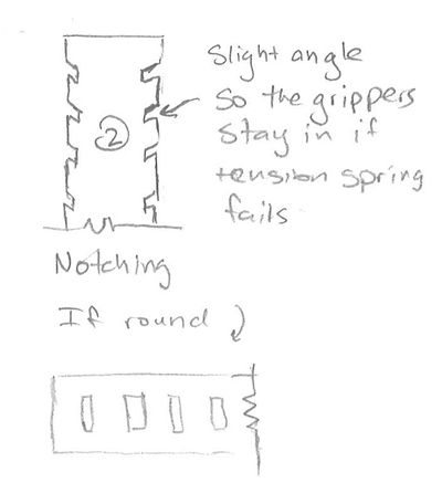
- A knurl could be added to the lower portion of the support arm to increase the coefficient of friction between the grabber and the support. If the knurling is insufficient, would could add notches in the support and tabs to the fingers to lock into the notches.
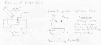
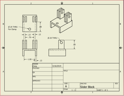
Design Concept 3 - Slider Mechanism
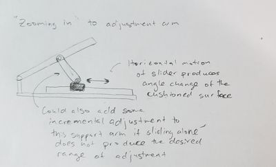
- Option 3 is certainly the simplest of all the designs; it also the most reliable, and has the least likelihood of malfunction. It has much fewer moving parts which removes many opportunities for problems down the road.
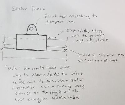
- This option involves horizontally moving the lower end of the support arm by means of a slider block to achieve the desired angle. (See images above)
- There would need to be some means of "squeezing" the slider to the railing to prevent it slipping from its position once the desired angle is achieved. This would probably be done with a set screw with a handle, a pin with holes along the rail (pin could be spring-loaded or manual), or a quick release clamp of some sort.
- If the needed working range of motion could not be achieved by the slider alone due to size constraints, adjustment could also be incorporated into the support arm itself. Making the support arm longer increases the angle of the bed. Hypothetically, if we need a max angle of 60 degrees, but moving the slider only gets it up to 30 degrees, the support arm could then be lengthened to produce the desired angle. The arm could have a few length options, with each option allowing for a different subset of the overall needed angle range of motion. Changing the length of the support arm could be accomplished by having a rod within a shaft. Holes would be drilled through each component to allow a pin to be placed between them. Different hole alignments would then produce different lengths.
- Changing the length of the support arm may or may not be needed. A decision will be made from analysis of a working computer model of our design.
Evaluate concepts/Select candidate
- The table below ranks the three design concepts discussed above on a scale of 1 to 3. We chose this scaled so that we could compare which design was the best, middle, and worst in each category. In an effort to rank these designs as to how well they meet the criteria given to us by the family, the categories chosen closely resemble the design parameters listed earlier in this web page.
| Reliability | Size | Adjustability | Ease of Operation | Replicability | Total | |
|---|---|---|---|---|---|---|
| Design 1 | 2 | 2 | 1 | 2 | 2 | 9 |
| Design 2 | 1 | 3 | 2 | 3 | 1 | 10 |
| Design 3 | 3 | 1 | 3 | 1 | 3 | 11 |
- While all the designs have their pros and cons and the scores are very close, design concept 3 is the best choice even when weighing all parameters equally. Realistically, all the design factors do not carry the same importance. This bed is not meant just for comfort and ease of adjustment; its primary function is to help prevent the infant twins' choking while laid down. Due to the nature of these circumstances, reliability is the most important factor. Any mechanism complications that have any possibility of not working perfectly every single time produce troubling considerations of the worst case scenario. Seeing that design 3 has the highest score overall, and specifically in the reliability category, it is the clear choice to pursue as we move forward with more detailed design and fabrication.
Detailed Design
After much consideration and thought on this topic, we decided to go with Design Concept 3, the Slider Block Mechanism. It is the simplest and most sure-fire adjustment mechanism. While it may be somewhat more difficult to adjust than the other designs, this minor inconvenience is far outweighed be the fact that there is much less possibility of the mechanism not latching or releasing properly and consistently or otherwise malfunctioning. The first two designs would allow for one handed adjustment, but the number of moving parts creates more room for error and more possibility of having problems down the road. Having long term dependability in mind, the slider block design is the best choice. The remainder of this section will describe this design in more detail, as well as describe some analysis that we conducted in order to ensure its functionality and safety.
Detailed Description of Selected Design
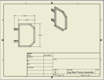
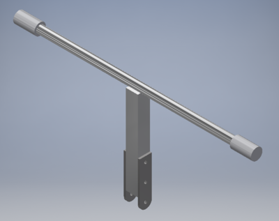
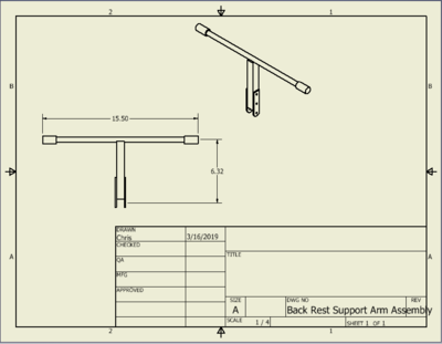
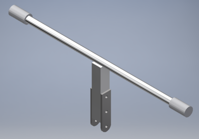
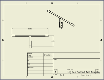
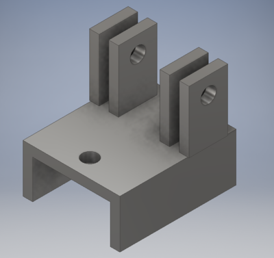
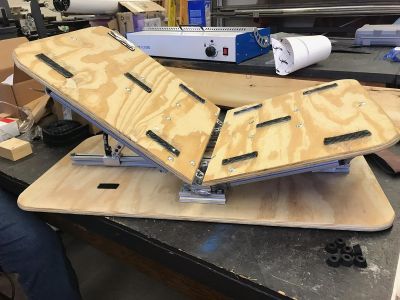
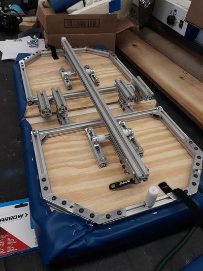
- The Slider Block Design that we have chosen is fairly straightforward at a surface level. The bed top will consist of two movable sections, one portion that adjusts from the waist up, and another portion that adjusts from the waist down. Both sections adjust in the same manner, so almost all design discussion that can be applied to one side can be applied to the other. The only exception to this rule is the length of each section; the foot side will be slightly shorter than the head side.
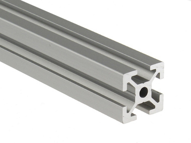
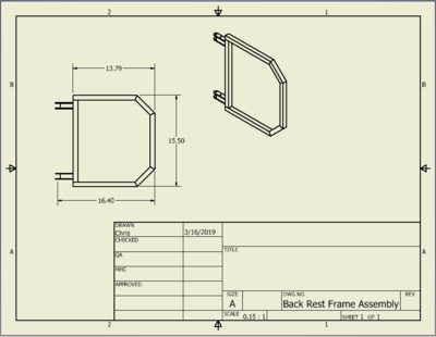
- Shown below is an image of the completed 3D model of the design. We are including it here as visual reference for the remainder of this design description. Please note that this model does not include the cushioned surface of the bed, which will be discussed momentarily. Also shown is an image of T-slotted aluminum extrusion, referenced frequently in the following section.
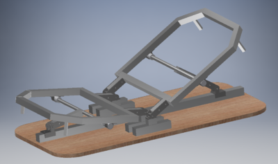
- Now that you have a visual image of the design, we will discuss the components from the bottom and working up and around over the next several points.
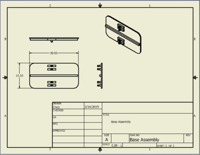
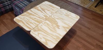
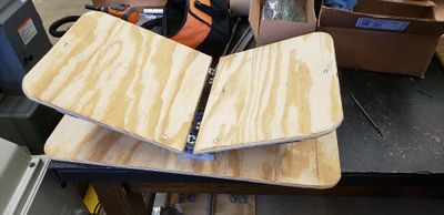
- The base of the bed will constructed from 3/8" plywood. The size of the wood is 15.5" wide by 30" long, the approximate size of a standard bassinet. The corners will be rounded, all edges will be routed with a round-over bit, and the surfaces will be sanded to prevent the wood from snagging on sheets, blankets, etc. and to prevent the wood from splintering. Rubber feet will be glued to the bottom of the wood to help keep the bed in position
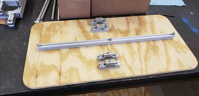
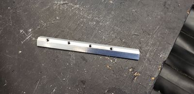
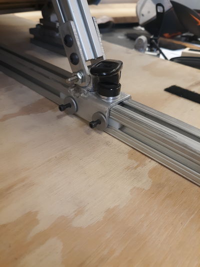
- Attached to the plywood base via carriage bolts will be 1"x1" T-slotted aluminum extrusion. Carriage bolts were selected because their low-profile rounded heads allow us to keep the bottom of the bed mostly flat and free of sharp edges. The 1" extrusion is slightly bigger that the 20mm extrusion used elsewhere to provide additional clearance for the moving parts that support the frame of the bed. There is one long rail the runs down the center of the plywood end to end (minus 1/2" at both ends). This rail will serve as the track for the slider blocks to run on. There are 4 smaller blocks that act as risers for the hinges of the bed pivots.
- The slider blocks will be made out of 1/8" aluminum plating. They should fit perfectly over the 1" extrusion, no slop but not too tight. There will be vertical plates on top of the sliders that will allow for us to make a pivot between the slider and the support arm. The clamp that squeezes the slider to the rail will be constructed from a "cam-locker" style clamp. These clamps are commonly found on bicycles, both on the seat height adjustment and as a quick release for the front wheel on many higher-end bicycles. They operate with a handle which has a circular end. The circular end is pinned off-center to the end of a threaded rod. When the handle is pushed down, the off center end forces the end of the threaded rod away from the other end, placing a tremendous clamping force on whatever is in between. Placing the slider block and the rail between the ends of the clamp will squeeze them together quite nicely and provide a solid connection that will not slip.
- The hinges are pre-made and will be ordered. They are designed specifically for use with aluminum extrusion and come with all the nuts, bolts, and brackets that are needed to install them. After much discussion, we decided that using these hinges was a better option than trying to make our own. The hinges are fairly expensive, but the difference in cost justified when considering their precision, functionality, and strength. Each half of the bed will have two hinges, one on each side. Note that the hinges in the image above are not the same as what will be ordered, they are merely placeholders to demonstrate the function of the bed.
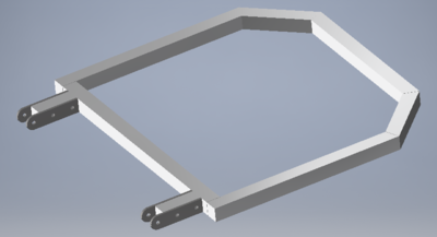
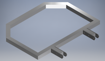
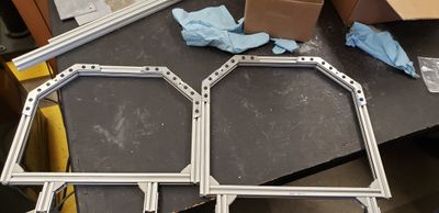
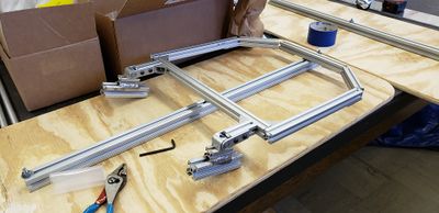
- Attached to each hinge is the main frame of the bed. Both ends are constructed of similar frames, varying only slightly in length. The frames will be constructed with 20mmx20mm aluminum extrusion. All the 90 degree joints will be attached with brackets that are readily available for purchase and provide extremely solid connections. The 45 degree joints will be assembled using brackets that we plan to make ourselves. Pricing for 45 degree brackets was extremely expensive, and we will have some aluminum plate left over from the slider blocks that can be used to make these brackets.
- The frames of the bed will each be supported by an arm. The arm is attached to the underside of the bed frame with an 1/2" aluminum rod that will ride in a Delrin bushing at each end. The bushings will be fixed to the frame with common pipe straps, which are inexpensive and available at any hardware store. We designed this with two frames so that both the head and the foot of the bed can be angled upwards. This creates a cradling effect, and the child will naturally slide towards the middle. The parents previously had problems with the children tending to slide to the bottom of the bed because the whole bed was at the same angle. This two-sided design should help to remedy that problem.
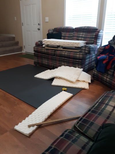
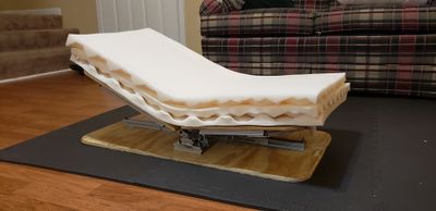
- On top of the frames will be the cushioned surface of the bed. We plan to use 3/8" plywood again for the upper surface, carefully shaped foam that provides comfort and stability for the children will be placed on top of the plywood. After the foam is on the wood, a vinyl fabric will be wrapped snugly over top of the foam and stapled to the underside of the plywood. This vinyl fabric will be waterproof, which is beneficial for obvious reasons. The family can place their on sheets or blankets over top of the vinyl for comfort. This way, when a diaper inevitably leaks or other circumstances arise to soil the linens of the bed, they can easily be removed and washed, the vinyl surface below can simply be wiped clean, and the foam will not absorb any undesirable substances.
- On a final note, we plan to have positive stops extending down from the underside of the frame, so that when the bed is folded completely flat it will rest on the surface of the plywood base. This will allow us to fashion a latch that hold the bed closed. We will also attach a carry handle to the side of the base, so that the whole bed can be collapsed and transported as a solid, compact unit.
Analysis
The following section describes three analyses we did on our design to ensure that it would produce the desired range of angle adjustment and would be strong, sturdy, and safe for the twins.
Engineering Analysis 1
- The first analysis we did pertained to the placement of the pivots and the travel distance of the slider block.
- Using geometry and a vector model of our design concept, we were able to write a computer program in MatLab that allowed us to choose certain parameters, and solve for the remaining. This enabled us to rapidly zero in on the best dimensions for our final design.
- The image below depicts the final resulting equations after we applied some admittedly tedious mathematics to our conceptual design.
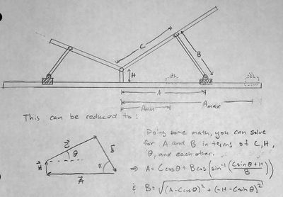
- With the equations shown in the image, we wrote a program (a portion of which is shown below, top) that allows you to choose dimensions for C,H,the maximum and minimum desire angles, and the maximum length of A (all as defined in the image above). Once you pick these constant parameters, the program tells you how long B (the support arm) should be, as well as how far the slider block must travel (A_travel) to produce the desired angles. With this output, it was very simple to play around with the input parameters and make decisions on the key dimensions of the bed. The program's result for the parameters we decided on is shown below(bottom).

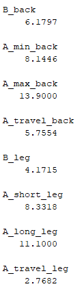
- With the parameters that we chose and the output from the program, we were able to create a 3D model of our design that worked the first time without a great deal of hassle and reworking of the model.
Engineering Analysis 2
- The second analysis we did was a calculation of how much force the hinges of the adjustable bed will have to support at various angle adjustments.
- For these calculations, we assumed that each of the twins weigh 30 pounds. Obviously, that is significantly more than a prematurely born child less than a year old would weigh, but we want our design to be far stronger than it needs to be so that it is very rigid and safe.
- Shown below are some images of the diagrams and calculations used to derive the necessary equations to determine the forces acting on the hinges. We left everything symbolic and without actual numbers to make it simpler to create a computer program later on.
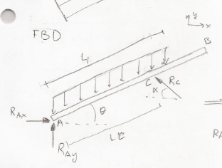
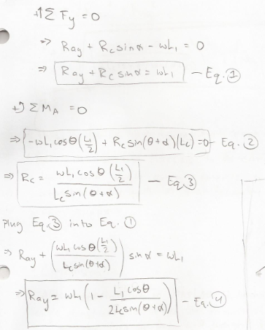
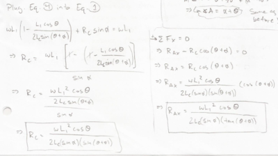
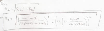
- Using the equations shown in the images, we constructed a computer program using MatLab that allowed us to experiment with different weights and angle configurations to determine the greatest possible force that the hinges would have to withstand. Shown below is the code that we wrote to calculate the force on the hinges.
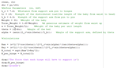
- After experimenting with the parameters in MatLab it became apparent that smaller angles produce more force on the hinges. The family informed us that approximately 30 degrees is the angle they would most likely be using frequently. At that angle, the hinges are only supporting about 5 or 6 pounds. However, if you decrease the angle of the bed to 10 degrees, the hinges must support a whopping 115-120 pounds. This large amount of force is due to the fact that the bed and the support arm are nearly horizontal, but the pin supports are having to hold up the purely vertical force of the child's weight. Although this seems like daunting amount of force, the hinges we have selected will have no problem withstanding it.
Engineering Analysis 3
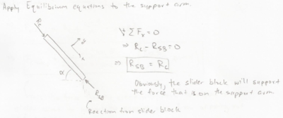
- The third thing we analyzed stems directly from the second analysis. We need to know how hard the slider block will have to be squeezed against the rail to prevent slipping. During Engineering Analysis 2, we had to solve for the force provided by the support arm. If you apply equilibrium equations to the support arm, it is obvious the support provided by the support arm is also what is pushing on the slider block. Shown below is a free body diagram and a simple equation to show that the force provided by the support arm to the bed surface is equivalent to the force that support arm applies to the slider block
- Now that we know the force that it is acting on the the slider block, it is simple to derive an equation to determine the clamping force needed to keep the bed at the desired angle without the slider block slipping from its position. Shown below is the diagrams we created, and the derivation of the required clamping force. Again we left everything symbolic to make coding a generic program much simpler later on.

- Using the equation shown in the image above, we created another program that calculates the necessary clamping force to prevent the slider block from slipping and allowing the angle of the bed to change when the child is laid on it. The code that we created is shown in the image below. We again assumed the weight of the child to be 30 pounds for the same reasons as stated above. We also assumed the coefficient of static friction between the slider block and rail to be 0.9. Most sources list a coefficient of 1.05-1.35 from aluminum on aluminum contact, but we decreased this to introduce another slight factor of safety into our design.
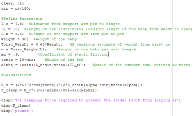
- After experimenting with the numbers in MatLab, we found that a larger clamping force is needed for smaller angles, as expected. This is due to the same reason as in Engineering Analysis 2. At a normal operating angle of about 30 degrees, the needed clamping force is only about 8.5 pounds, but when you decrease the angle to 10 degrees, a much larger 210-215 pounds of clamping force is needed. We do not think that this large force will be a problem for the clamp style that we have chosen because it allows the operator a great deal of leverage, so they will not actually have to apply this great amount of force. Also keep in mind that all of these calculations are intentionally over-estimates of the forces that will actually be applied in order to remove any doubt that the bed will perform the tasks that are required of it. If in the fabrication process we see that the clamping force is insufficient, we will "rough up" the surfaces of the slider block and the rail to increase the friction between them, and thus decrease the needed clamping force
CAD Drawings
- Images of 3D models of the bed, major assemblies, and critical parts, and 2D drawings of major assemblies and parts are included in this section. For the sake of not being overly verbose, every small part will not be shown individually, but rather in sub-assemblies of the overall design. Also, only images with captions will be shown here. Please refer to the above section entitled "Detailed Description of Selected Design" for a description of each part's functionality.
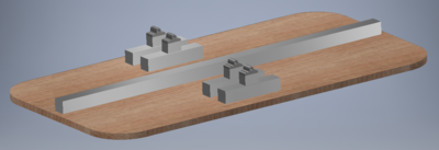
- Put all these parts together and you get the fully assembled model shown below.
Bill of Materials
- Below is the bill of materials for this project. It is broken down by suppliers, and both beds are accounted for in the quantities and prices.
Assembly Instructions
The final product will be delivered to the family fully assembled. We waited until we delivered the bed to add side cushions to make sure we get them in the proper location. We will give brief description of how we assembled the bed, but more detail with pictures can be seen in the next section.
- We built the beds from the bottom up. We did this so that we could build the beds on top of the wooden bases instead of building the bed and having to fit them to the base properly. This allowed us to make sure all the components were properly aligned with little to no hassle.
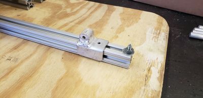
- The bases were made from half inch plywood. We attached a 29 inch stick of 1 inch square aluminum extrusion down the middle of each base. This serves for strength, rigidity, and a track for the adjustment mechanism.
- We added risers for each pivot of the bed. This allowed us to elevate the main frame slightly, so that all the moving components could fold flat between the top of the bed and the base.
- The frames were made from 20mm square aluminum extrusion. All the pieces were attached using purchased brackets or brackets that we made ourselves.
- The wooden tops, as well as the bases, were attached to the frame using 1/4"x2" carriage bolts. This allowed us to have a low profile head that could not be felt through the foam topper. It also alleviated the tediousness of having to have a wrench on both sides when tightening down the nuts.
- The hinges were purchase and simply attached to the frame. They were a crucial part of the design, and they functioned wonderfully.
- The supporting adjustment arms were also made from 20mm extruded aluminum. The pivots on the bed frame side were made from a 1/2" aluminum rod that was welded perpendicular to the support arm. Each end of the rod fit inside a cylinder made from Delrin, a very smooth and durable plastic. The Delrin was bolted to the underside of the bed frame using pipe straps. The pipe straps keep the end of the support from sliding, and the rigidity of the Delrin prevents the straps from hindering the needed rotation of the aluminum rod.
- The slider adjustments were made from a scrap piece of 1-1/4" square aluminum tubing. The piece we used had 1/8" walls, so the inside dimension was 1" and it fit perfectly over the 1" extruded aluminum track that runs the length of the bed. The clamps we used are modified bicycle hub lockers. We cut the length down to what we needed, and fabricated special threaded inserts that matched the shape of the inner profile of the 1" extruded aluminum. The precise shape allowed the slider to move freely without a great deal of slop. The cam shape of the bicycle parts allowed for a "quick release" style of adjustment. Open the lever and the slider moves easily to adjust the angle, close the lever and the bed becomes very sturdy. As you can see in the above sections, the clamp has to exert a great deal of force when the bed is at low angles. The clamps could not be adjusted such that they were tight enough to hold this great force at low angles, and still be loose enough to adjust easily. So, we cut blocks of wood in such a way that none of the three dimensions were the same. The block could go under a part of the bed frame to allow for 3 incremental adjustments at small angles. Anything more than the largest adjustment from the blocks, and the clamps hold just fine.
- The cushions were made from an egg shell style memory foam mattress topper. Each bed has 3 layers of 1-1/2" memory foam. The foam is covered by a sheet of vinyl. The vinyl is very reminiscent of the type of material found in cribs, on a dentist's chair, and such like. It is wrapped over the foam and stapled to the underside of the top sheet of plywood. This secures the foam and the vinyl. We were concerned that the foam might want to shift under the vinyl over time, which would be very problematic considering that the vinyl is not easily removed and reattached. We added some adhesive back velcro to secure the foam to the plywood before covering the foam with the vinyl to avoid this issue.
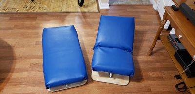
- The side cushions were made from the left over mattress topper. They were wrapped with the same vinyl material in a very Christmas-presenty sort of way. We attached the side cushions when we delivered the beds so that we could have the mother place the children on the beds and see exactly where they needed to go. These side cushions serve the purpose of keeping the babies centered in the bed so that they are unable to roll out of the beds and get hurt.
- The final touches to the bed were an extra velcro strap to keep the beds held closed in the flat position for ease of transportation. This was necessary because you cannot reach the clamps to lock the beds in place when they are positioned fully flat. We also added two carry handles to each bed in a position that makes the bed easy to place in and out of a pack-and-play crib. They also allow the beds to be carried somewhat like a oversized briefcase if and when they need to be transported.
Fabrication Process
Please note that we built these beds together, not one at a time. So, in some places you will see pictures of both beds, and in other places you only see one. However, anything we did to one bed, we did to the other, so they are exactly the same. Also note that the order shown here is not necessarily the exact order. Some small things could be done ahead of time before they make their appearance in the overall assembly process.
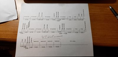
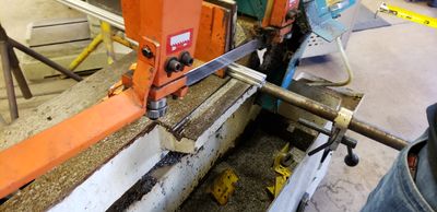
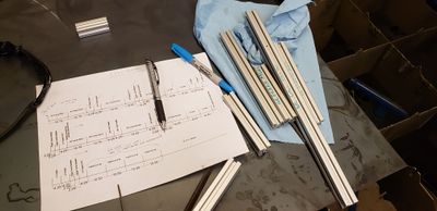
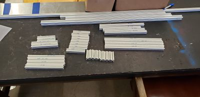
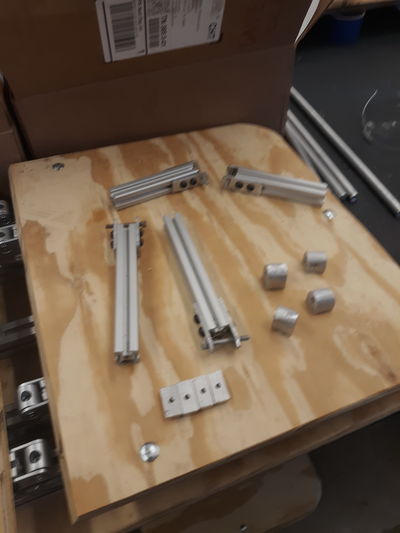
- Before we started making anything, we had to cut the extruded aluminum to the lengths we needed. What you see below is a drawing we created to prevent having a lot of wasted material, an image of the horizontal band saw we used to cut the material, and couple pictures of all our cut pieces.
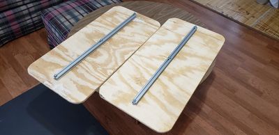
- The first things we needed were the bases for each bed. We started with plywood, then added the slider track, and then the hinge risers.
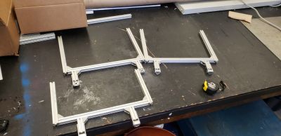
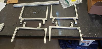
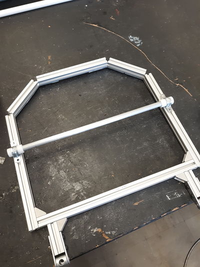
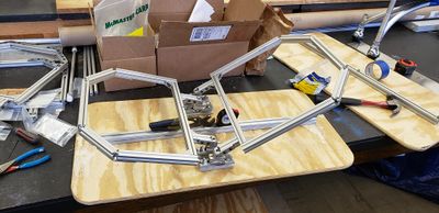
- We then started assembling the main bed frames. There are several pictures below of them going together.
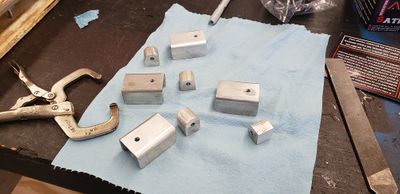
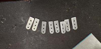
- It was cheaper to make our own 45 degree brackets than purchasing them. We 3D-printed a pattern of the bracket with holes in it so that we could trace out the shape we needed and punch a piece of sheet metal so our holes would align perfectly.
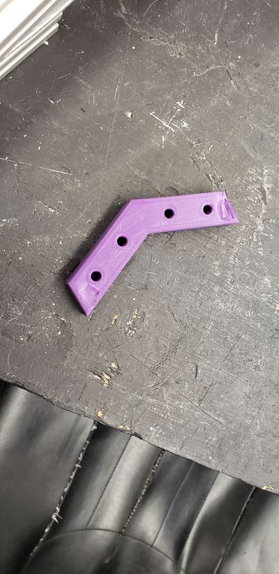
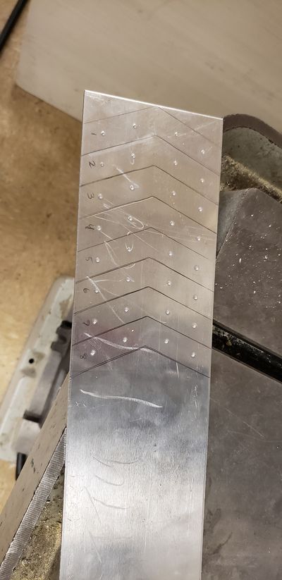
- It was cheaper to make our own 45 degree brackets than purchasing them. We 3D-printed a pattern of the bracket with holes in it so that we could trace out the shape we needed and punch a piece of sheet metal so our hole would align perfectly.
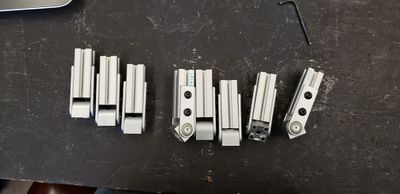
- These are the hinges that we purchased after we had assembled them.
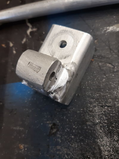
- We also attached the support adjustments to the back of the frame. You can also see how the hinges attached to the frame in this image.
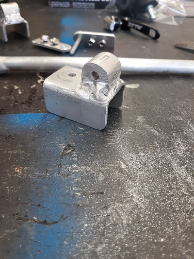
- The aluminum rod in the image above ended up bending during initial testing due to the large forces in play at low angles. We redesigned for a shorter rod, shown below, to alleviate this problem. Also shown below are the Delrin bushings we made for the aluminum rod to rotate in.
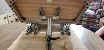
- Once the frames were assembled, we attached them to the bases at the hinge points
- Once we knew the frames fit like we wanted, we took them back off to drill holes and attach the top plywood with carriage bolts. With the plywood on, we reattached the frames to the bases.
- With the bed taking shape, it was time to start creating the adjustment. The main part of this adjustment is the slider block. A description of this part can be found in the previous section.
- The other part of the adjustment was the support arms. We made our own pivots to attach the supports to the slider blocks. We made them to closely resemble the brackets that came with the purchases hinges, and they worked out great.
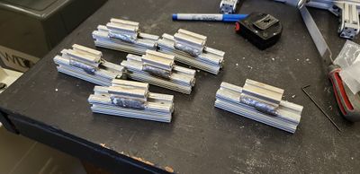
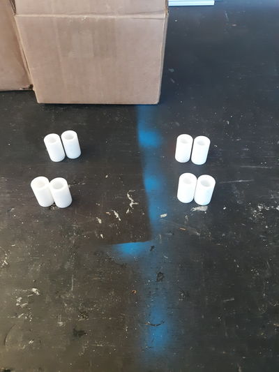
- Shown below is a step in making the threaded inserts that go inside the aluminum track. In the picture, it had not yet been cut into pieces, but you can see their final length in the image above. We actually had an issue with the threads in these not holding up to the strength of the clamping force. We had originally made the inserts out of aluminum, but had to remake them out of steel to keep the steel threads of the bike clamps from pulling the threads out of the inserts.
- The first image below is a repeat from earlier, but it shows a good image of the bicycle clamps we used on the sliders. The second image below shows an alternate angle of the bicycle clamps. It also shows a Delrin runner we made for each slider to help reduce slop and binding.
- Once the adjustment mechanism was finished, all that remained was adding the cushion to the top surface. We put some adhesive velcro on the top plywood to prevent the foam from sliding under the vinyl. We cut the foam out of a 1.5" thick memory foam mattress topper, making three layers for each bed.
- With the foam secured in place, we could then cover the beds with the vinyl material. This is what they looked like after they were covered. The upholstery work turned out right nice in our opinion, at least for a couple of engineering students.
- Once we had the vinyl on, we were almost done. We took the bases back off so we could put a few coats of polyurethane on them to give a more finished look. The image below is what the underside of the fully assembled bed looks like with the base removed.
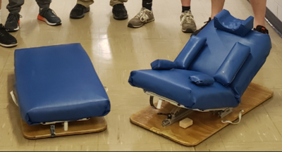
- After the polyurethane was applied, we reattached the bases to the frame of the bed. We added two handles, made of nylon strapping, to each bed. They were placed such that the parents can easily place the beds in and out of a crib or anywhere else for that matter. We added a velcro strap to hold the beds flat when being carried by one of the handles for transport. We made some side cushions that we did not put on until we delivered the bed so that we would get them in exactly where they needed to be. The side cushions serve to keep the baby in place, and prevent them from rolling out of the bed. The picture below has the side cushions just placed on the bed in an approximate position, but nonetheless shows our completed project!
Testing and implementation
- We tested various aspects of our project as we went through the process of building the beds. We only ran into two major issues. The first was the support arm rod being bent when simulated weight on the bed. After it happened, we realized that we should have expected it. We had calculated the force in the support arm for use in calculating the necessary clamping force for the sliders. We assumed that the clamps would be our 'weakest link'. We never even thought to see how that force affected the pivot rod. After the rod had bent, we did a simple calculation and realized that the bending stress produced from the loading was approximately double the yield strength of the aluminum rod. No wonder it bent! We shortened the rod as much as we could, giving us a fairly large factor of safety, and we knew that the rod would not bend again.
- The other problem we ran into was in the sliders. When we raised the beds to higher angles, the inserts that we made were catching inside their track due to there being a little bit of slop in the sliders. We added a Delrin runner to each slider that runs in one of the side groves of the 1" extruded aluminum track. This runner prevented the slider from rocking up when the bed was pulled to higher angles. This helped the binding problem a great deal, and made the bed function more smoothly overall.
- Once we had worked out these couple of bugs, we were confident in our final product, and we were ready to deliver.
- We brought the beds to the family and they worked great! We attached the side cushions in their proper place, and the children fit perfectly on their new beds. The mother thought the beds would fit perfectly side by side in the twins' pack-and-play crib.
- The mother was very pleased with the results and was very appreciative to have these new adjustable beds to better fit her children's needs. She said that when her twins outgrow the problems they are having, she will return the beds to an organization that will be able to place them in the hands of another family that needs them.
Photos of Completed design
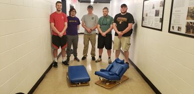
- Shown below is the group picture we took with our completed project just before we left to deliver the beds to the family.
- See the previous sections for more pictures
Instructions for safe use
These beds are structurally safe and sound. The use of the side cushions for the safety of the children is at the discretion of the parents. The only warning for the person operating the adjustment is to keep fingers clear of the pivot points when adjusting, especially when lowering the angle. Failure to observe this precaution could result in receiving a painful pinched or smashed finger.