Adjustable Mobility Device
Abstract
Therapist: Karyn Henderson
We are designing a replacement device for mobility and child safety. The child in question (name not listed for the sake of privacy) is not capable of using his legs and so uses a low-riding plastic toy called a Crawligator™ to move around his home. Unfortunately, as he grows, he will become too large for this toy, which is currently banned for sale in the United States because children were attempting to descend stairs on the toys and so a new, larger one cannot be purchased. Since the home contains only one stair, our design will follow a very similar structure to that of the Crawligator™ but will be larger and have adjustable scale so that, as he grows, his parents can adjust the size of the toy to accommodate his size.
The primary challenge with creating anything for child use is ensuring the safety of the user. It must be secure and must have minimal risk of pinching or rolling over clothes, carpet, and digits. It must be light enough for a child between the ages of 18 months and 4 years to propel but strong enough to withstand rolling across hard wood floors, carpets, tiles, and a single stair.
Within these parameters we will have designed several possible replacement mobility device adjustment mechanisms onto which contoured plastic covers may be placed that resemble the initial toy.
Team Members
- Isaac Friedman
- Nathan Large
- Derek Overbay
- Larry Adams
- Shane Terry
Photo of Team
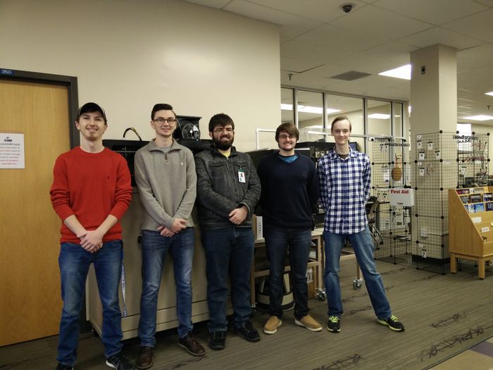
From left to right: Derek, Larry, Isaac, Shane, and Nathan
Årgos Designs
Problem Statement/overview of the need
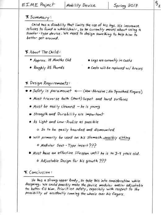
Design Specifications
1. List of design specifications. Some of these must be quantitative and measurable. You should be able to use these to compare design options.
The general design should reflect elements of the existing device as that is what the child is already used to. Safety is our number one concern when approaching this device. It must be light enough to be maneuvered by the child. For the body, the contours should remain relatively the same so that the child can use a device similar to the one he already has. The goal is to provide a adjustable device that will last until the child is 3~4 years of age.
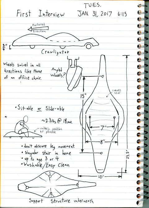
Background research
1. What exists already, similar products 2. availability 3. identify gaps in existing products or technology to be addressed
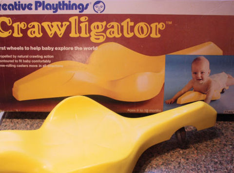
"The Crawligator belly scooter is one of the icons of the Creative Playthings era--an era where keeping the kid from inadvertently scooting down the stairs and cracking his melon open was the parents' job, not some pesky government agency. Now, between the vintage toy and design collectors, the nostalgia folks, and the parents of kids with mobility issues or developmental delays, these rarities sell for quite a bundle. I think the well-preserved box on this one is gonna favor the collectors, but we shall see." -http://daddytypes.com/2011/12/03/whoa_crawligator_in_a_box_baby.php
This existing product is no longer available due to it being outlawed. The reason for this outlaw is that children would often use the device to fall down stairs, leading to injury.
This existing device performs well and the only lacking factor is that it is not adjustable to the child's size.
Conceptual Design
Summarize your conceptual design process. Develop at least three concepts.
Design Concept 1
- Description
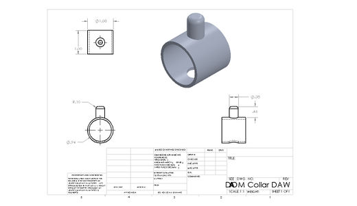
Similar to the mechanism that makes "easy-ups" work, the collars will click into place and allow it to expand. The pins on top of the collars will allow for the plastic peices to fit together and on to of the Crossbar.
- Schematics

Design Concept 2
Beveled Gears will twist along the crossbar members, therefore allowing it to be adjusted with, like concept 1, the plastic pieces on the top.
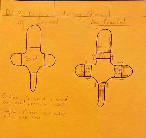
Design Concept 3
The device expands through the guided expansion of balloons. Similar to blood pressure cuffs, the balloons can be inflated manually to expand the device.
Design Concept 4
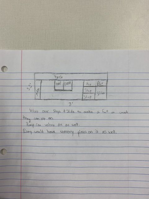
A removable plastic shell is placed over a rigid metal frame, allowing for different shell options.
Evaluate concepts/select candidate
Use a decision matrix or similar tool to compare designs against project specifications Discuss winning candidate
Design Concept 1
Pro: Simplistic design, cost efficient, lightweight, and should ideally be able to support the weight of the child.
Con: Involves manufacturing of many custom parts and tolerances would have to be minimized.
Design Concept 2
Pro: Simplistic design, sturdy, and should ideally support the weight of the child
Con: Involves manufacturing of many custom parts, would be the the heaviest of concepts, safety risks exist due to the many rotating parts, most complex of the designs, and the tolerances would have to be minuscule.
Design Concept 3
Pro: Lightest of the designs, modular in a gradient rather than incremented, and no complex part that endanger the child.
Cons: Involves many custom parts, guiding system itself is quite complex, and the inflatable balloons add a major point of failure.
Design Concept 4
Pro: Simplistic design, cost efficient, lightweight, easily available parts, and should ideally be able to support the weight of the child.
Cons: Would require more than one shell to be made and stored.
Concept 1: Pro: 4 Cons: 2
Concept 2: Pro: 3 Cons: 5
Concept 3: Pro: 3 Cons: 3
Concept 4: Pro: 5 Cons: 1
Logically, Concept 4 is the most effective as it provides the most pros while sacrificing the fewest cons.
Detailed Design
Description of selected design
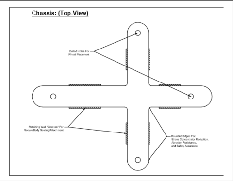
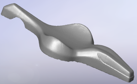
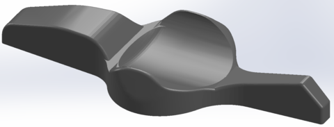
Solid frame with interchangeable shells.
Detailed description of selected design
Analysis
Analysis 1: Internal stress analysis of frame
Analysis 2: Frame cross section optimization
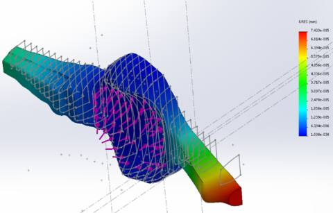
Analysis 3: Shell modeling and FEA
Engineering analysis 1
The first step of designing our frame was to determine what loads it would experience. Our goal is to provide a usable device until the child is 4 or 5, so we used CDC survey data to determine the maximum expected weight of the child at 5 years, rounded up to 55 pounds. At this point, we chose 2.0 FOS and modeled the frame as two independent beams supporting 100% of the load each, in order to come up with a worst case failure condition.
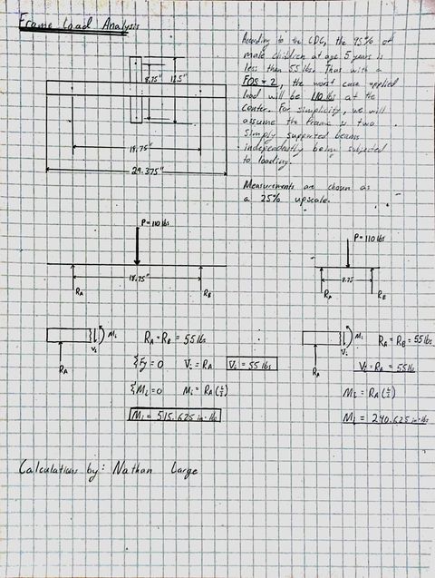
Our results showed the internal moment and shear forces that the frame would have to support.
Engineering analysis 2
Once we had the maximum expected shear and moment, we needed to determine what cross section of stock would be best for constructing the frame. For each of three cross sections, we used the maximum bending moment equation in terms of required thickness, h. Initially we used the yield stress value for 1018 steel because it is readily available and easy to work with.
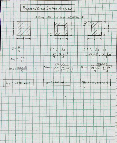
Our results showed that each of these cross sections could handle the expected loading at a thickness less than half an inch. We discarded the I-beam option because one this small would be difficult to work with and relatively heavy. At this point the frame was to be difficult to machine due to its small cross section and also fairly heavy. We decided to test whether aluminum would be a better material option by applying previous equations using the yield strength for aluminum.
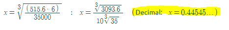
The calculation below is for for a solid square beam of 6061 Aluminum to determine the height to support the moment applied. Because the answer was close to a half of an inch, we chose 1/2" for the dimensions of our cross section. Using 27.5" worth of material it comes out being around 0.67lbs.
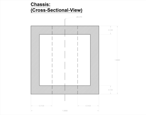
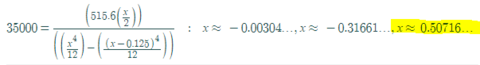
The calculation below is for for box tubing of 6061 Aluminum to determine the height minimum height to support the moment applied. We needed at least 1/2" so we chose to increase it to 1" just for simplicity. It wouldn't affect weight too much and we would have more room to work with for attaching the castors.
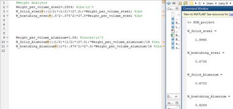
Below is Matlab code written to determine the weight for each chasis design,
1. 1018 steel bar 1/2" x 1/2"
2. 1018 steel box tubing 1/2" x 1/2"
3. 6061 aluminum bar 1/2" x 1/2"
4. 6061 aluminum box tubing 1" x 1"
Engineering analysis 3
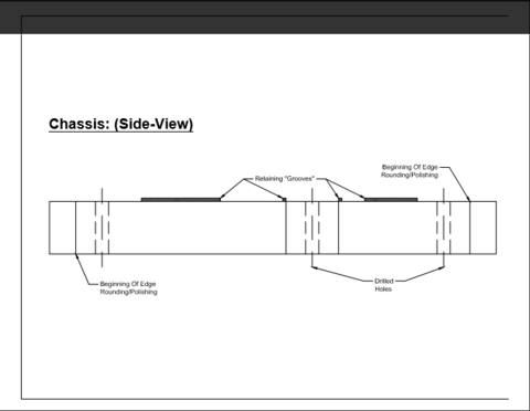
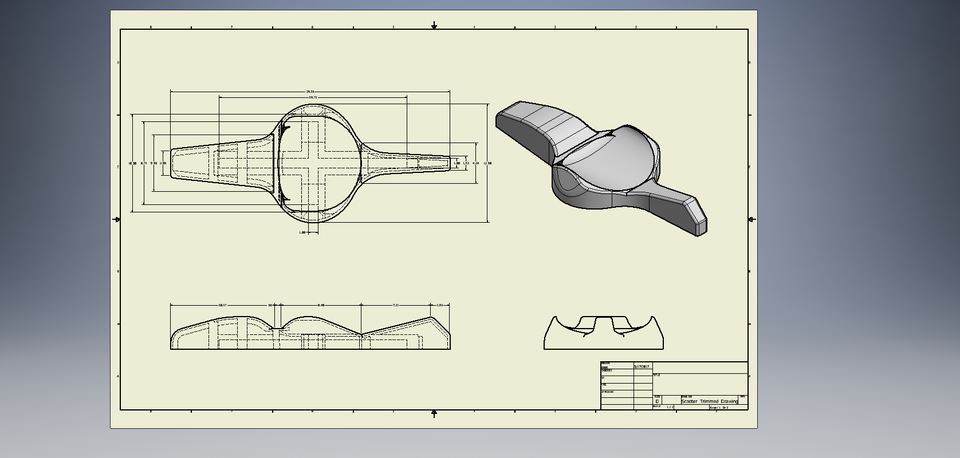
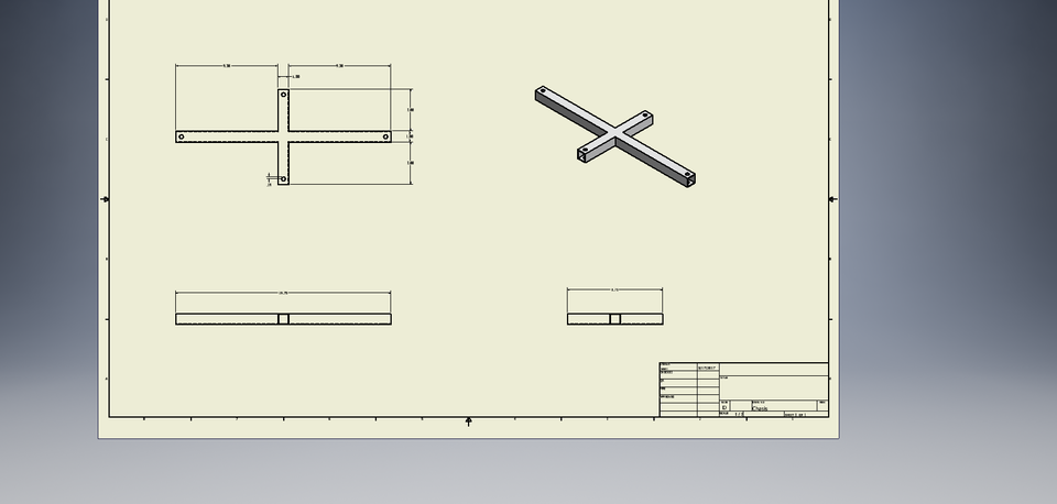
CAD Drawings
Insert drawings of all parts and the assembly
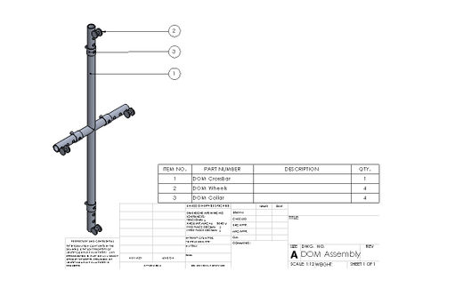
Bill of Materials
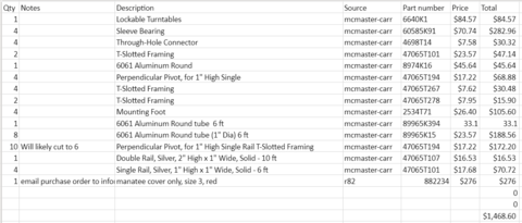
The photo above is the bill of materials for 1 Chassis and 1 Shell. Due to the extreme cost to produce one shell by either Vacuum forming or outsourced 3-D printing, we will produce only one shell at the current time. The weight of the part is 1.6 Kilograms and would therefore only require 2x 1 kilogram rolls of 3-D printing material. The cost for one 1 kg spool of ABS (Amazon.com Hatchbox) is $23.99 so the total would be $46.98 for the necessary in-house material cost. However, the only location on campus that can produce a print of sufficient quality and size is the industrial printer in the STEM center. Permission would be needed and suffice time would be required in the case of failure.
In-house 3-D Printing Modeled Crawligator Shell - $50.00
Assembly Instructions
Inventory:
1x Shell
1x Aluminum chassis
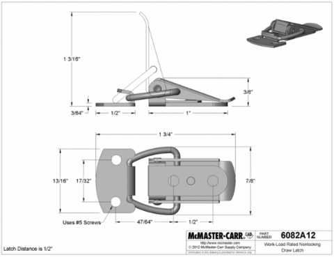
4x Check latches to make sure they are correctly mounted to their respective pieces.
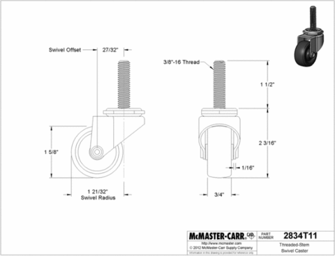
4x Check castors to assure that they are threaded and mounted correctly.
Step 1:
Align the shell on top of the chassis making sure that the t-shaped aluminum chassis slides into the plastic inlet.
Step 2:
Flip latches into place mounting the plastic shell to the chassis. Force should be required to get the latch into place, but do not use an excess amount of force. If an excess amount of force is experienced, try readjusting the chassis and shell before trying again.
Step 3:
Inspect the device to make sure that all of the latches are in place and the assembly feels solid.
After Step 3 the device should be ready for use.
Fabrication Process
Fabrication of chassis and initial assembly
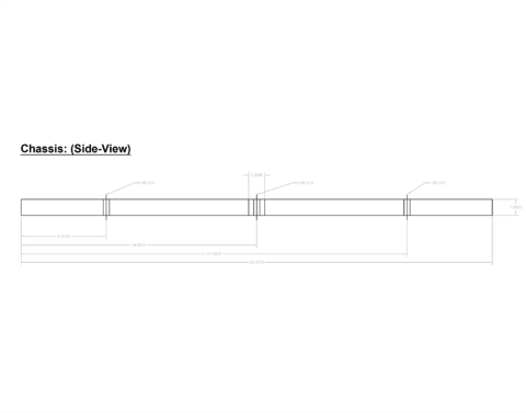
We started with 6' of aluminum box tubing.
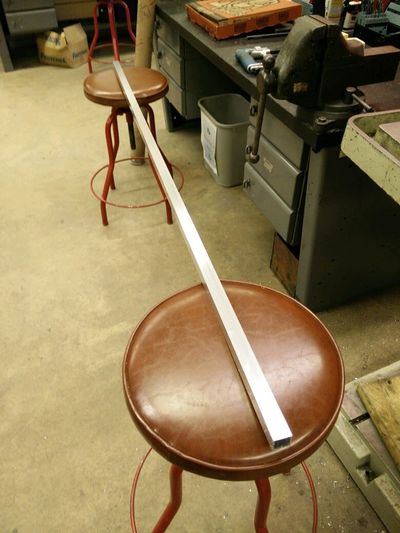
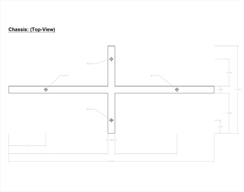
First: We need to cut the tubing in to three pieces. One piece was to be 19.75" and the other two were to be 5.75".
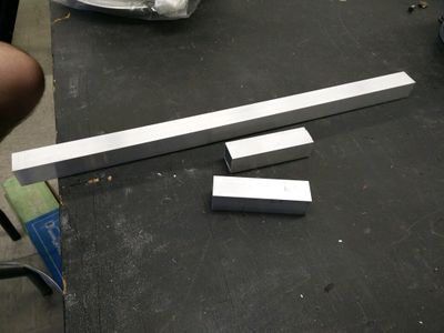
After the pieces were cut and the holes were drilled for the casters to be attached, the ends needed to be filed down so no rough edges were left.
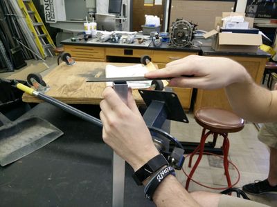
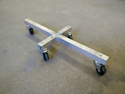
Then the pieces are welded together to form the t-shape chassis that we need.
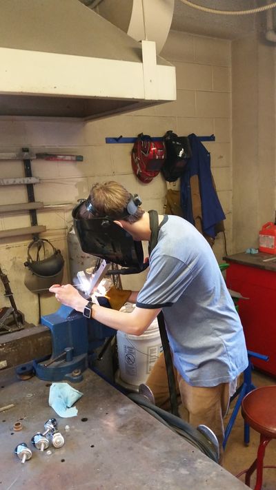
After the welds are finished and smoothed down, we needed to cut down the threads for the casters so they would fit with the shell attached.
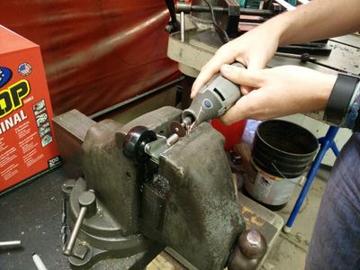
The casters are then attached using the holes we drilled and two nuts per caster. We used two nuts to prevent the caster from coming loose after time.
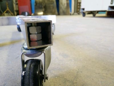
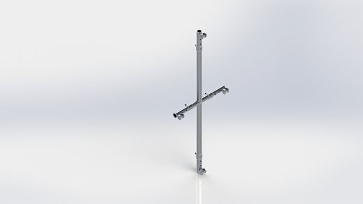
The final assembled chassis is shown below...
Fabrication and Production of shell
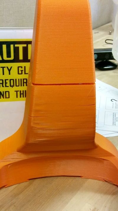
The shell was 3D printed using TTU's 3D printers. Below is a cross section of the part while it's being created.
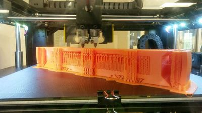
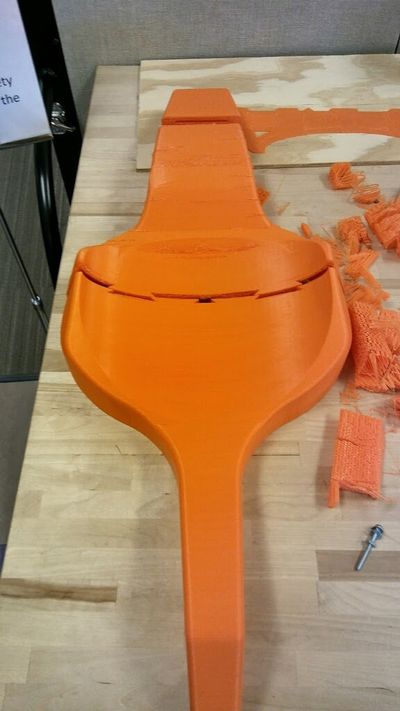
After the print was finished
Testing and implementation
Describe testing, delivery, how used/received by the family
Testing
We tested the chassis to see if it would support the maximum load we needed it to. We needed it to hold 55 lbs. The chassis was able to hold 120 lbs very easily without any deformation. We also tested the casters to see how smoothly of a transition they would make from hard floor to carpet. They had no problem whatsoever with the transition.
Photos of Completed design
Insert pictures of the final product
Instructions for safe use
Provide a clear summary of safe use for the family. Do not use the device unless supervised by an adult that has been fully understood the safe use of this product.