Adjustable Rowing Bike F14
Abstract
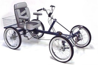
Students in the Special Education Program at Cookeville High School have to maintain physical fitness, but also should have fun while doing so. A bike powered by a rowing motion increases upper body strength and is fun to operate. The Special Education department has two rowing bicycles that cannot be used anymore. One is powered only on the backwards pull motion, is not adjustable, and does not have foot rests or fittings. The other is difficult to operate, does not move fast, and again does not have foot rests or fittings.
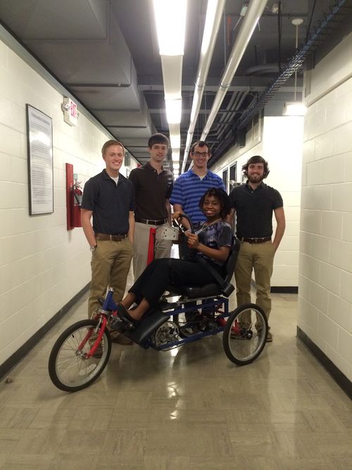
Team members
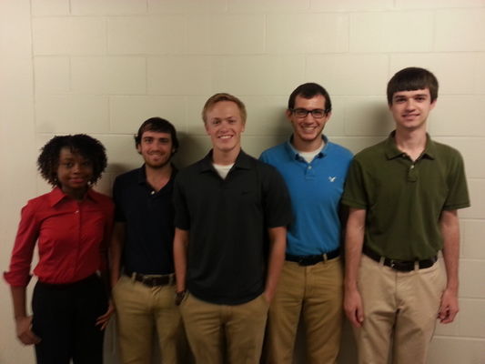
- Matthew Powelson
- William Schenk
- Derrick Davis
- Chimezirim Ibe-Ekeocha
- Riley Collins
Acknowledge help of others
- Perry and the civil engineering shop team
- Jeff and the mechanical engineering shop team
Problem Statement/Overview of the need
Summary
Our plan is to design a rowing bike that can solve all of the problems of the two current rowing bikes. It needs to provide power to the wheels on both the pushing and pulling motion, be adjustable for any student present and future, have foot rests and fittings for any students who cannot use his or her legs, be easy to operate, and move at a fun speed.
User Information
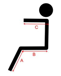
User dimensions:
- User 1
- Overall height = 55"
- A = 15"
- B = 14"
- C = 21"
- User 2
- Overall height = 58"
- A = 20"
- B = 19"
- C = 24"
Requirements
Primary Requirements
- Exercise upper body
- Provide appropriate resistance for user
- Travel through 33" doorway
- Adjust to fit user
Secondary Requirements
- Engage user through full range of motion (both pushing and pulling)
- Travel fast enough to be fun
- Coast backwards easily when pulled
- Actively engage lower body
- Be easy to maintain, durable, and fixable
Design Specifications
List of design specifications. Some of these must be quantitative and measurable. You should be able to use these to compare design options.
- Exercise the upper body specifically a bench press exercise such as a rowing motion
- Provide appropriate resistance for muscle grade 3 user
- Travel through 33" doorway
- Adjustable in order to fit users from 55" to 72" tall
- Provides power to the wheels on the forward and backward stroke
- Free to coast backwards when pulled
- Light weight in order to be moved easily
- Foot rest with staps
Conceptual Design
Summarize your conceptual design process. Develop at least three concepts.
Steering
| Design Concept #1 | Design Concept #2 | Design Concept #3 |
|---|---|---|
 |
  |
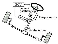 |
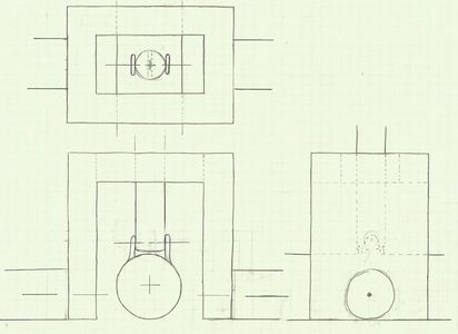
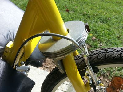
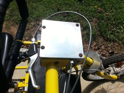
| This design employs pivotal steering. The column with the handle bars attached to it is fixed to a central shaft, but the column is allowed to pivot front to back for the rowing motion. when the user moves the column side to side, the central shaft rotates. At the end of the shaft is a tab where two rods are attached with revolute joints. One rod connects to the left wheel hub the other connects to the right hub. The wheel hubs are allowed to rotate about a vertical axis. When the central shaft rotates the rods push or pull the wheels inward or outward. | This is the existing steering design used on previous bikes. It uses cables wrapped around a spool. When these cables are pulled, the spool turns thus turning the front wheel. Pulling the cables is done by rotating the steering wheel | This design is a fly-by-wire steering concept. It combines the existing steer by cable design and the pivotal steering design. The steering wheel will turn a torque sensor which tells an actuator via wires or wireless to turn the central shaft. The central shaft will then rotate and operate the same steering mechanism as the forward section of the pivotal steering design. |
Drivetrain
All drivetrain concepts attempt to provide power on the forward and backward stoke of the rowing motion.
| Design Concept #1 | Design Concept #2 | Design Concept #3 | Design Concept #4 |
|---|---|---|---|
 |
  |
  |
 |
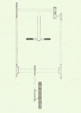
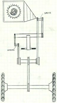
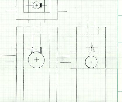
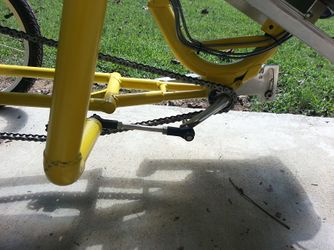
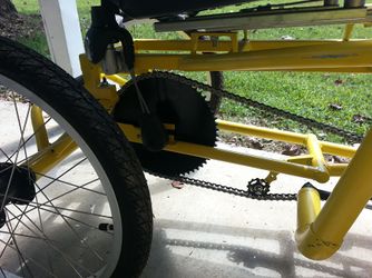
| This design achieves push and pull power through gears and free hubs. The column with the handle bars pushes against a box that is fixed to a lateral shaft. The column is free to move side to side within the box to allow for pivotal steering. When the box is pushed back and forth, the shaft it is mounted to rotates. On the left end of the shaft is a sprocket. A chain connects this sprocket to a free hub that is mounted to another lateral shaft located at the back of the bike. On the right end of the forward lateral shaft is a spur gear that meshes with another spur gear mounted on a parallel shaft. The gears reverse the rotation of the shaft and allow for power to be applied on the pulling stroke. On the other end of this parallel shaft is a sprocket. A chain connects this sprocket to a free hub that is mounted to the rear lateral shaft. The rear lateral shaft receives power from the free hubs which drives a sprocket mounted at the center of the shaft. Free hubs engage in one direction, so one free hub will be sliding freely while the other provides power and vice versa. A chain connects the sprocket at the center of the rear lateral shaft to a sprocket mounted on the rear axle which then provide power to the wheels or wheel. | In this design, the column that will be pushed and pulled will push against a box that is fixed to a lateral shaft. Perpendicularly attached to the bottom of the lateral shaft will be a bar. A chain will be attached to this bar and will run back to a free hub that is the same for Concept design #1. Another chain will run forward and be attached to a sprocket mounted on a lateral shaft up front. This lateral shaft will have gears similar to the gears in Concept Design #1, and the power will travel through the same design in Design Concept #1 past the gears in mesh. The sprockets used in this design will have spiral springs mounted on the side that will retract the chain when it's not in tension. | This design has been used on a previous bike in an attempt to provide power to the wheels on both the push and pull motion. The column that you are pushing and pulling will pivot about a revolute joint about three fourths of the way down the column. A link will connect the bottom of the column to the crank that is fixed to a sprocket. When the column is pushed or pulled, the crank will drive the sprocket thus driving the wheels. A bungie cord attached to the crank will overcome the toggle position of the crank. | This design is the same as the crank, however pedals like on a bicycle which will be operated by hand will provide the power. |
Frame
| Design Concept #1 | Design Concept #2 | Design Concept #3 |
|---|---|---|
 |
  |
 |
| This is a 4-wheel frame design. Pivotal steering will be required with this frame, and any of the drivetrain concepts can be applied to this frame. It is the most stable frame. | This is a 3-wheel frame with a single wheel in the front. Steering with cables would be the best for this design, and all drivetrain concepts would work on this frame. | This is a 3-wheel design with a single wheel in the back. We want to keep the steering in the front, so pivotal steering would also be required for this design. All drivetrain concepts would work on this frame. |
Recycled Components
| Adjustable Seat | Brakes | Wheels |
|---|---|---|
  |
  |
 |
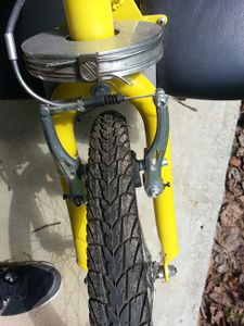
| The adjustable seat that is on the current rowing bike will be removed and used on our bike. | V-brake | Wheels |
Evaluate concepts/select candidate
Evaluation
Steering
Design Concept #1
Drivetrain
Design Concept #1
Frame
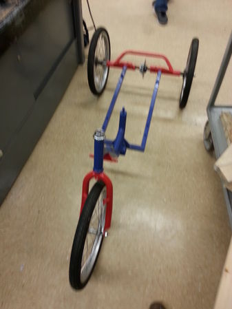
Design Concept #3
Detailed Design
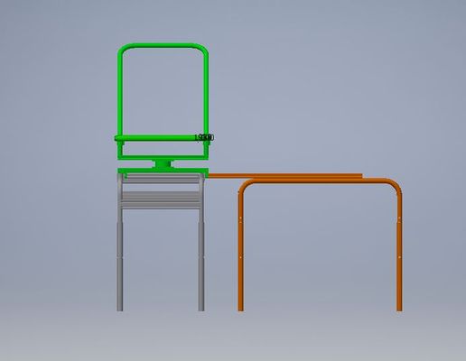
Description of selected design
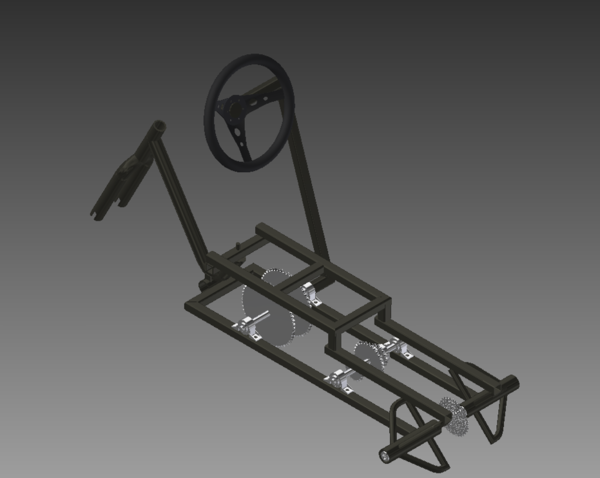
The design is broken into three major components: Steering, Drivetrain, and Frame.
- The steering system will primarily reused from the old bike. It utilizes a pull-pull cable system as shown in steering concept 2 above.
- The drivetrain is a modification of drivetrain concept 1 from above. It uses crossed chains to achieve the reversal of direction instead of the gears shown in the concept.
- The frame is a a modification of the frame from the old bike. It will be modified to allow for the new gear train and extended.
Detailed description of selected design
The new bike will reuse many of the components from the current bike and will essentially be an extensive drivetrain modification with other minor additions.
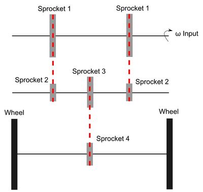
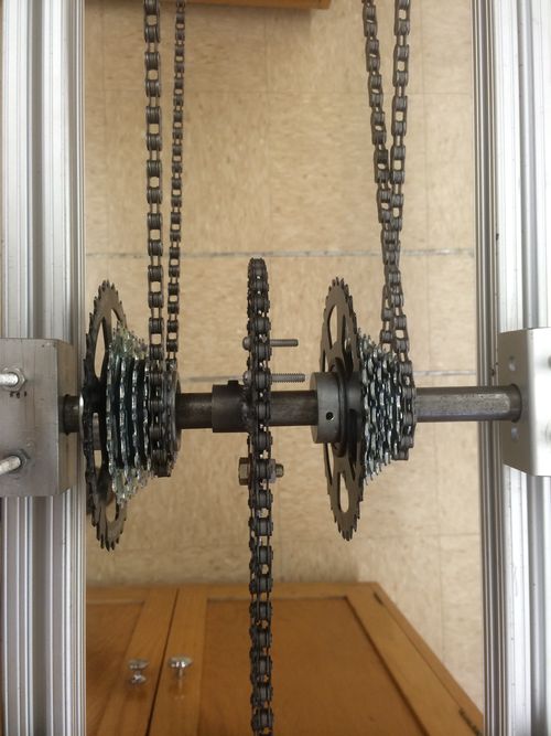
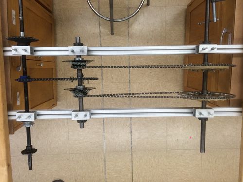
The drivetrain consists of three live axials. The first axle is the input. It is connected to a lever arm which is pushed/pulled by the rider. On this axial are two sprockets rigidly attached to the axial.
The second axle has three sprockets attached to it. One of the "Sprocket 2"s is chain driven off of "Sprocket 1" in the traditional way. The other "Sprocket 2" chain travels in a figure 8 path, reversing the direction of the motion. A guide block of low friction material will be placed at the intersection point to reduce the drag between the chains. The "Sprocket 2"s are riding on one one way bearings that engage in opposite directions
The third axle is attached to the wheels with a ratcheting cassette attached to the center. The cassette allows for noninvasive changes of the final drive gear ratio.
The front of frame will remain largely unchanged from the previous iteration of this bike. Will will extend the rear of the bike allowing the seat to be shifted back to make room for foot pedals. These pedals will allow the rider to actively engage their legs, a request of the customer. Furthermore, the extended frame will allow for the longer chain runs necessary for our gear train.
The steering will remain largely unchanged in our bike. Upon analysis, we found that the previous steering system provided sufficient turning capabilities and required minimal modifications.
Analysis
Engineering analysis 1
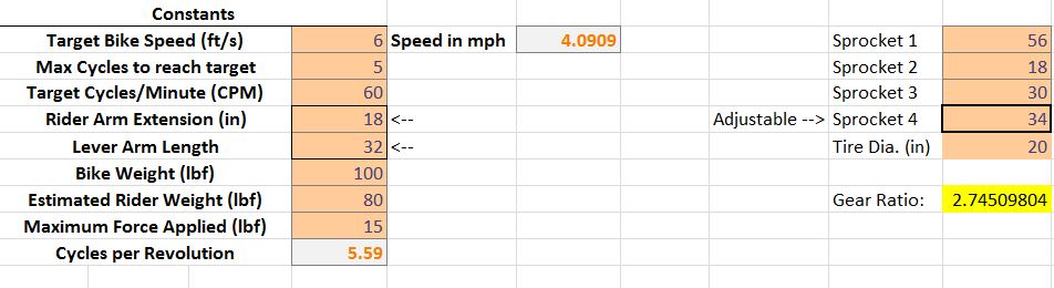
Gear Train Calculated
These are the primary inputs to the spreadsheet. Below are the primary assumptions and target outputs used for all of our sprocket calculations.
Assumpions
- Maximum rider arm extension = 18"
- Bike weight = 100lb
- Rider weight = 80lb
- Maximum rider pushing force = 15 lb
Target Outputs
- Target bike speed = 6 ft/s
- Max cycles to reach target speed = 5
- Target Cadence = 60 cycles/minute
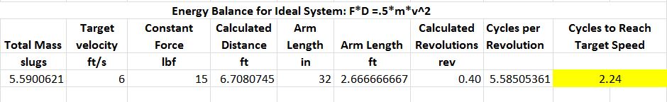
This calculation does a straightforward energy balance for an ideal system. We used it to get a general sense of what to expect from subsequent calculations. It takes the max force, bike mass, rider mass, and target velocity as inputs and solves for distance. The distance is then converted to cycles.
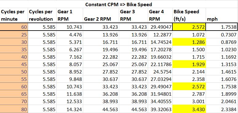
This calculation takes an input of cycles per minute and translates that to bike speed.
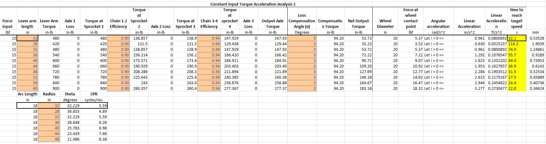
This calculation takes the length of the input lever arm, the inefficiencies of the different stages, and the standard assumptions listed above. It converts the force into a torque and runs that through the the gear train to get the torque at the output shaft. A generic loss term (discussed below) is then subtracted to take into account wheel friction and other losses outside of the drivetrain. The net torque is then converted back to a force acting at the point of contact on the road. At this point, the moment of inertia of the wheel is assumed to be negligible and acceleration is found using F = m*a.
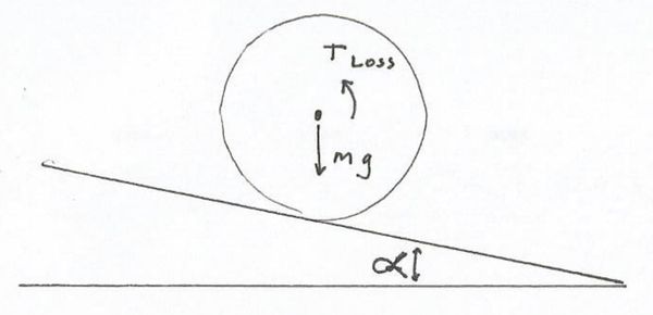
The loss term used in this calculation is equivalent to the torque required to keep the bike from rolling down an incline of alpha degrees as shown in the picture below.
Engineering analysis 2
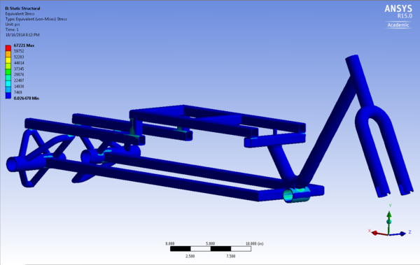
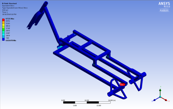
Frame Stress Analysis
This is a stress analysis for the frame in Ansys. We used a 100lb load to simulate the weight of the child.
Von-Mises Stress
Engineering analysis 3
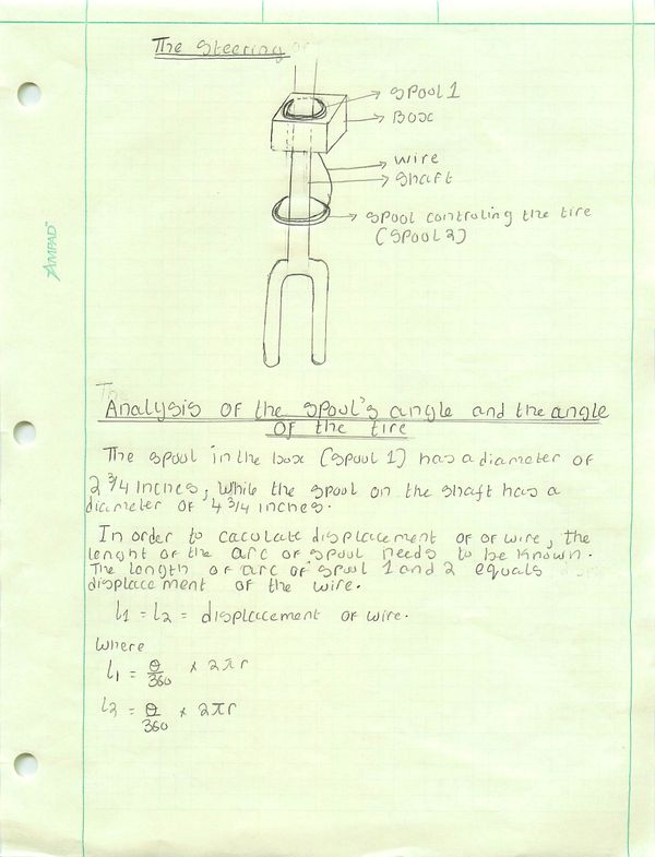
Steering Analysis
The steering, consist of 2 spools and a wire. A rotation of the steering wheel causes an equal rotation in spool1, this in turn causes a displacement of the wire and a rotation of the spool2.
Below is the analysis of the steering box.
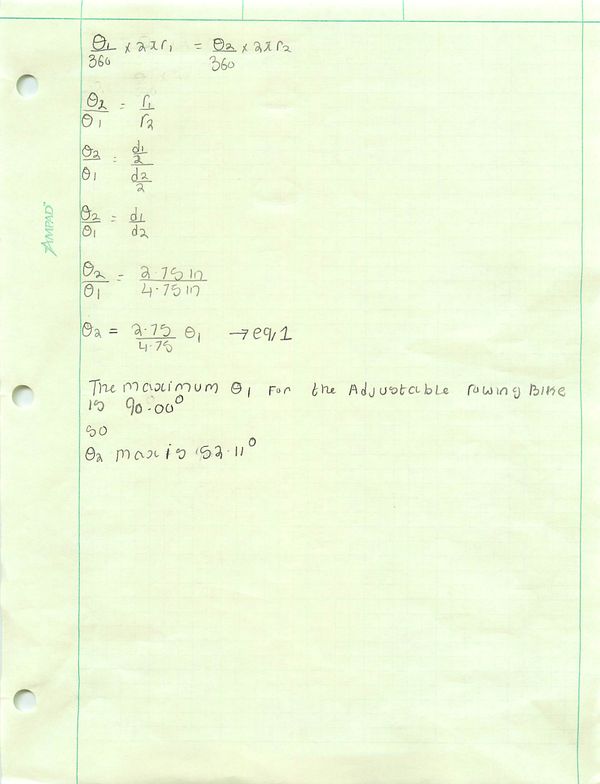
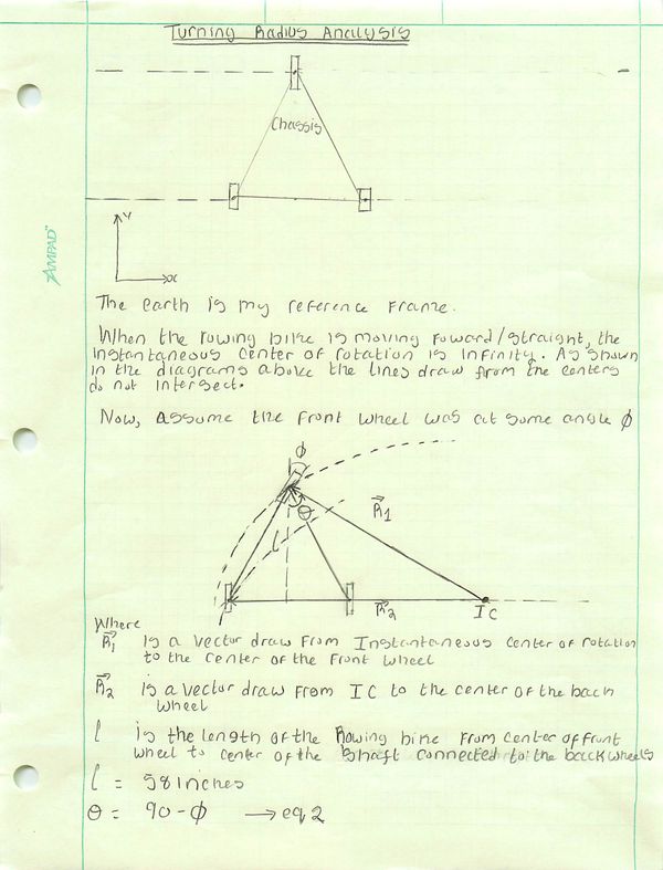
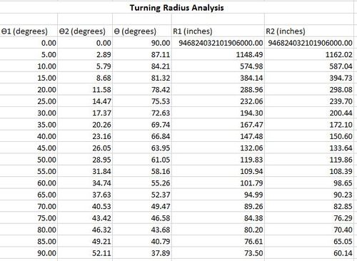
Turning Radius Analysis
Turning radius is the radius of circular turn that a machine can make.
There are different factors that can affect the turning radius
1) The distance between the tires ( the width of the Rowing Bike is 30 inches)
2) The spools (diameter and angle of rotation)
3) The speed of the machine ( for this Rowing Bike this will not be a major problem because the estimated maximum speed is 2.4mph)

In conclusion
The maximum angle of spool1 is 90 degrees and the estimated maximum turning radius at this angle is 73.50 inches.
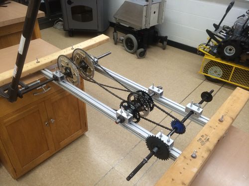
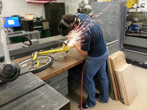
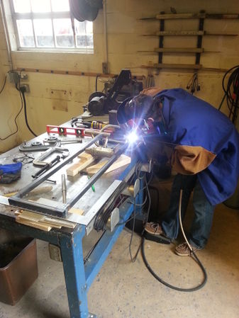
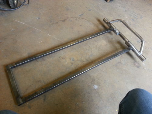
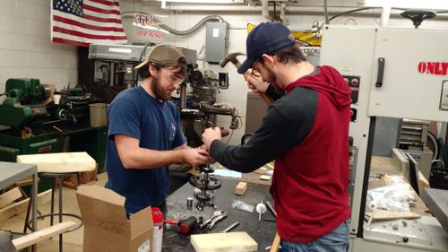
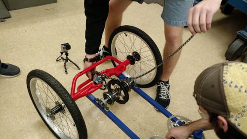
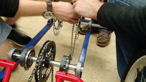
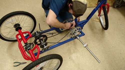
Prototype Process
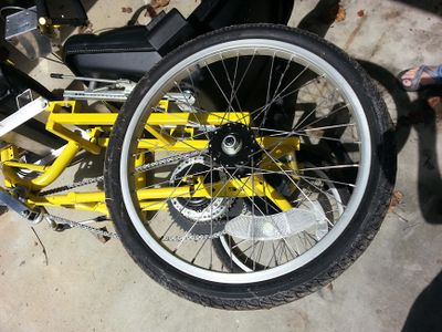
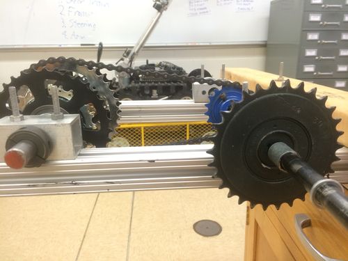
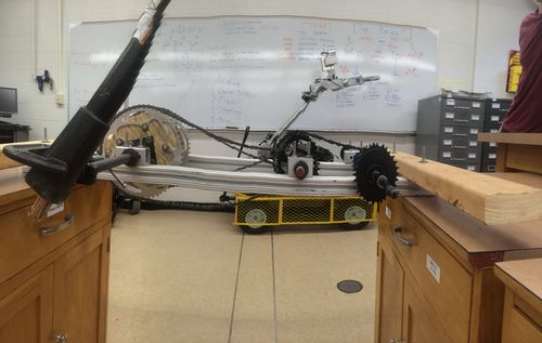
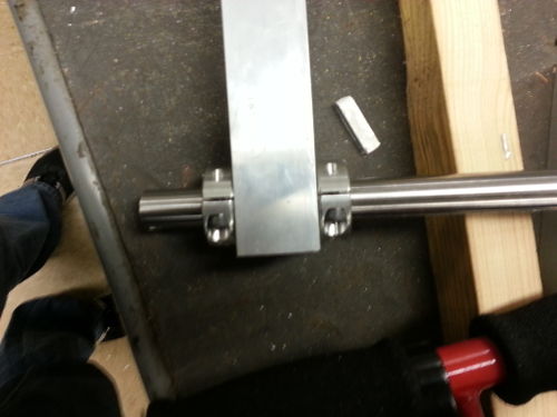
In order to test our drivetrain concept design, we built a prototype with parts from the Mechanical Engineering shop.
Testing proved successful and confirmed our design.
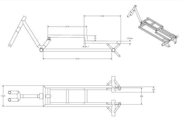
CAD Drawings
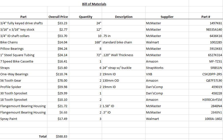
Bill of Materials
Assembly Instructions
- Disassemble the old bike: remove wheels, seat, seat frame, previous drivetrain, etc.
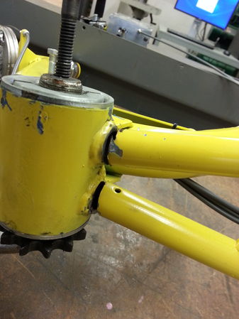
- Strategically chop up the old lower frame in order to implement our modifications
- Extend the lower frame of the old bike in order to accommodate our new drivetrain
- Make the same old seat frame but out of aluminum to reduce weight
- Modify gears in such a way so they can be fixed to the shafts
- Install our new drivetrain
- Install new aluminum seat frame
- Add foot pegs to the frame
- Reinstall previous steering
- Paint
- Test
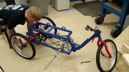
Fabrication Process
- Fabrication
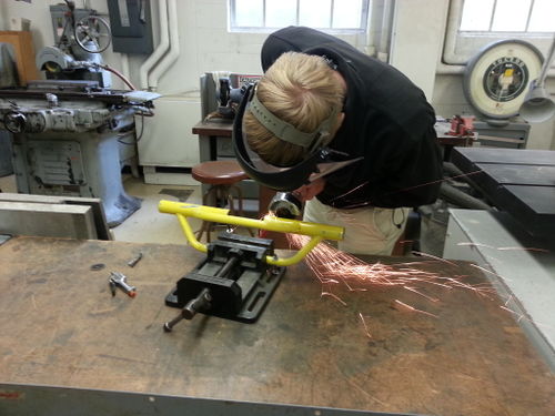
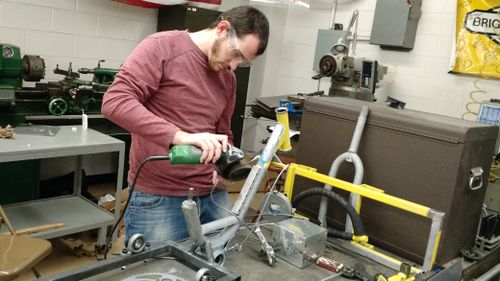
Beginning the disassembly of the old bike. Riley is using the cut-off wheel to chop up the old frame
The lower frame had to be removed so we could put our extended frame in
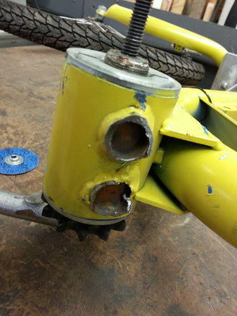
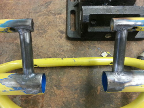
After the frame removal process
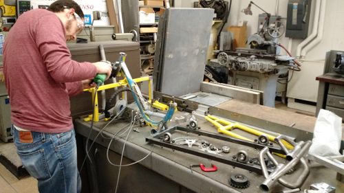
Will is removing some frame members that were oddly placed
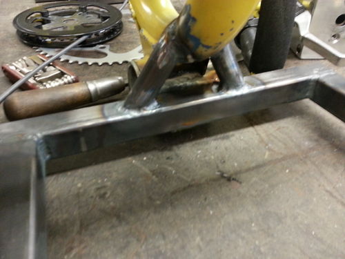
Riley welded in frame members that had better load bearing capabilities
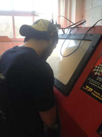
Riley using the sand blaster to strip the paint off the rear hub
After the rear hub was stripped of paint in the sand blaster
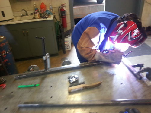
Riley welding up the new extended lower frame
Making sure the frame is squared up
Riley continuing to weld the extended lower frame
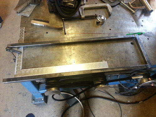
The finished extended lower frame. In an effort to reduce the length, we did have to shorten the lower frame later
This is after Riley welded the extended lower frame to the front of the bike, and he added additional members for support
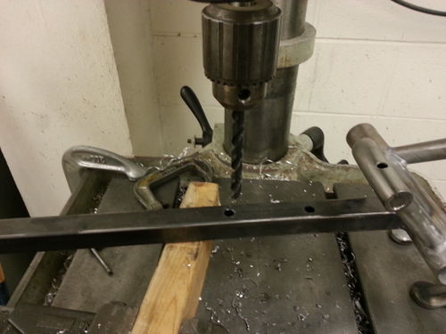
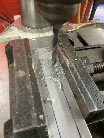
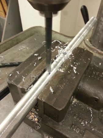
Drilling holes in the lower frame so we can mount the pillow bearings
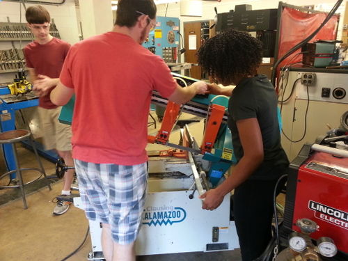
Colt and Chime cutting aluminum frame members for the new all aluminum seat frame
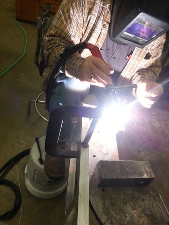
Getting some much needed help from Perry on welding up the aluminum seat frame
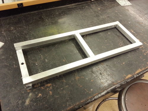
The almost finished aluminum seat frame. It just lacks the vertical members that attach it to the lower frame.
We are measuring how long the vertical seat members need to be
Cutting feet for the seat to be mounted to in order to elevate the seat a little
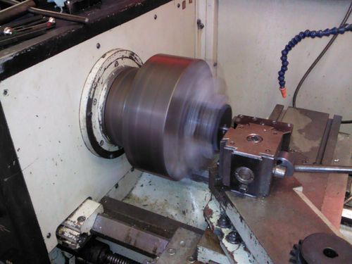
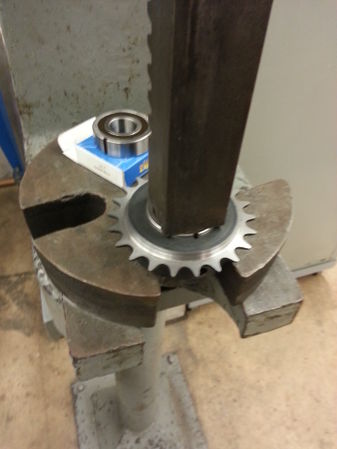
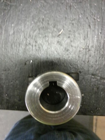
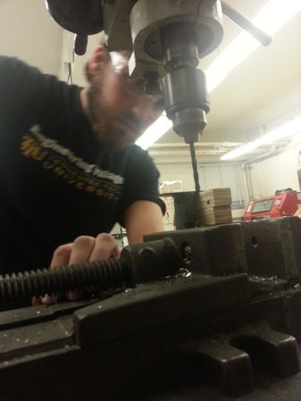
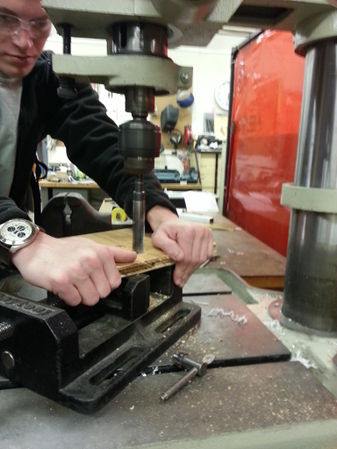
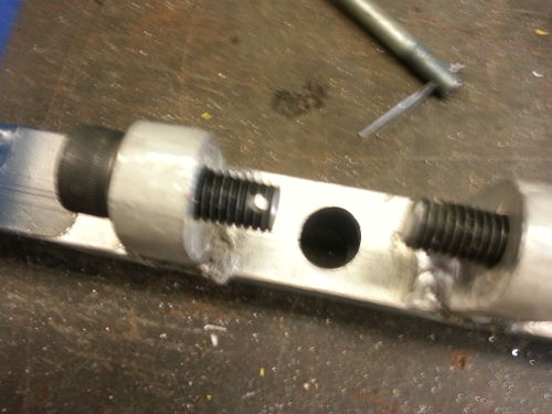
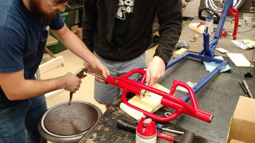
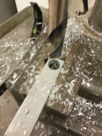
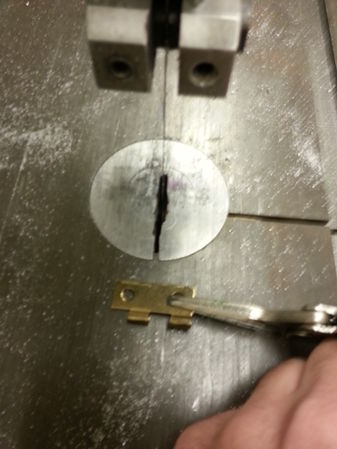
This gear is being bored out in order to house two one-way bearings
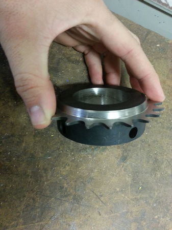
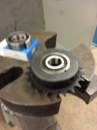
This is after the gear has been bored out and the teeth have been thinned to accommodate bike chain
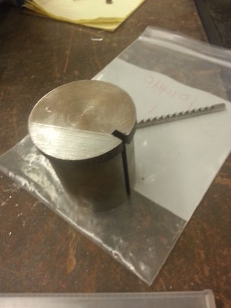
This is a custom bushing that Riley made that will allow a keyway broach to cut a keyway into the gears
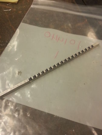
This is the 3mm keyway broach that we are going to use
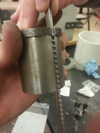
This is how the keyway broach works. The bushing rests inside the gear, the broach is pressed through the slot on the bushing, and the teeth on the broach cut the gear
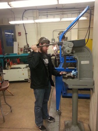
Riley using the press to push a keyway broach through a gear in order to cut a keyway
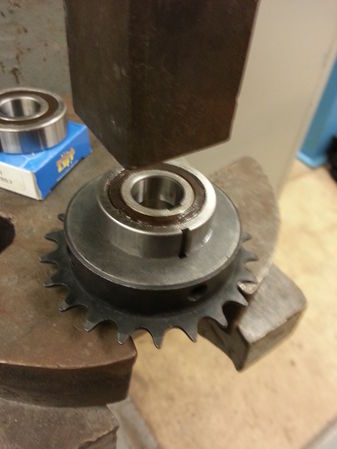
Press fitting the one-way bearings into the gears. You can see where we cut a keyway into the gear that matches up with the keyway on the bearing
Pressing the bearing
Finished press. We pressed two one-bearings into each gear. You can see the second bearing in the background
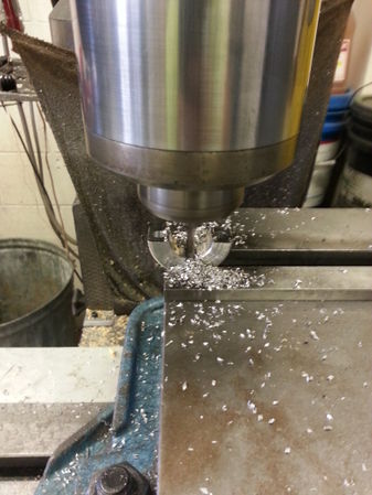
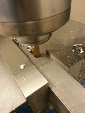
Using the miller to cut keyways into the upper half of the shaft collars that will be welded onto the chainring spiders
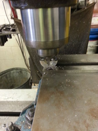
More milling
The finished product after milling
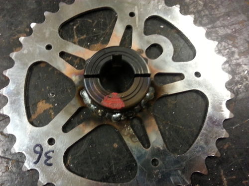
We welded a shaft collar to a sprocket in order to fix it to one of the shafts. We only welded the bottom, so we could clamp the upper keyed half of the collar down onto a key
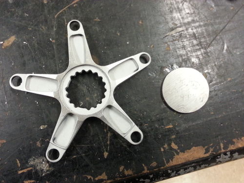
For our large chainrings, we had to order "spiders" in order to mount them to the shafts. Here, we are modifying the spider so that we can weld a shaft collar to it
We cut out circular disks in order to have a flat surface to weld the shaft collars on to
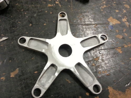
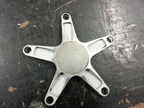
This is a "spider" after the disk has been welded onto it and sanded down
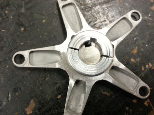
Before welding, we used a small piece of shaft in order to get the right alignment of the shaft collar
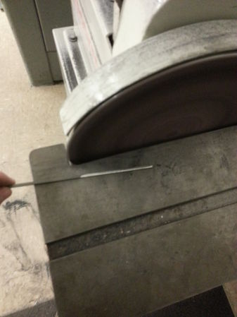
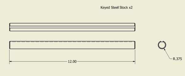
Trimming down some key stock to make keys for the keyways
Colt stripping the old paint off the reused parts of the bike.
Sandblasting the remaining paint off.
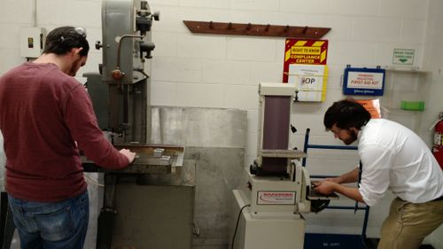
Colt and Riley hard at work following all of the important safety rules.
Riley drilling mounting holes into the chain tensioner
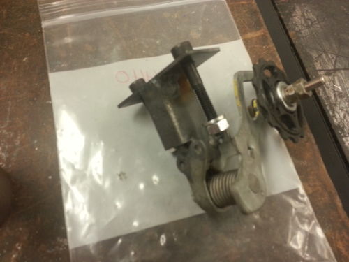
The finished chain tensioner that will allow us a change the gears on the back sprocket
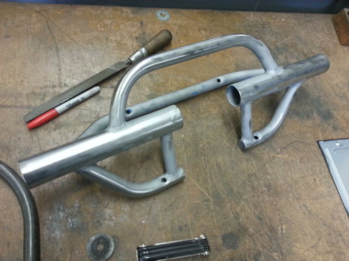
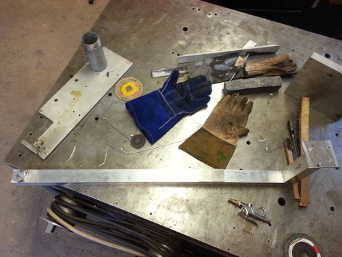
Riley using the miller to cut slots into members that will be used for the foot rest
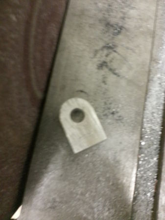
Mounting tabs for the foot rest to mount to and pivot around
We cut the old foot rest in two, so we could install our adjustable foot pegs
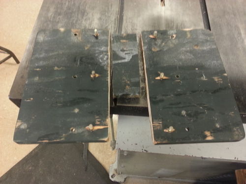
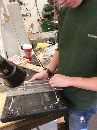
Riley and Will drilling holes in the board that the cushions will attach to
Riley drilling holes into the foot rest supports for the cushions to mount to
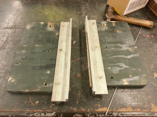
Seeing if the holes we just drilled line up with the bolts we secured through the board
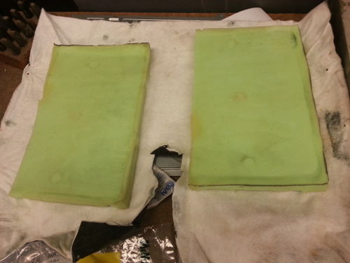
The old cushions and leather that we will reuse
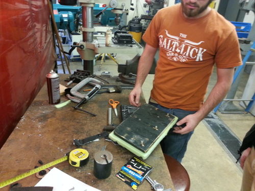
Putting the cushions back onto boards
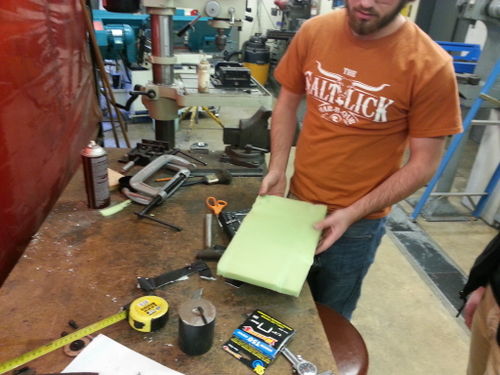
We used spray glue to keep the cushions in place
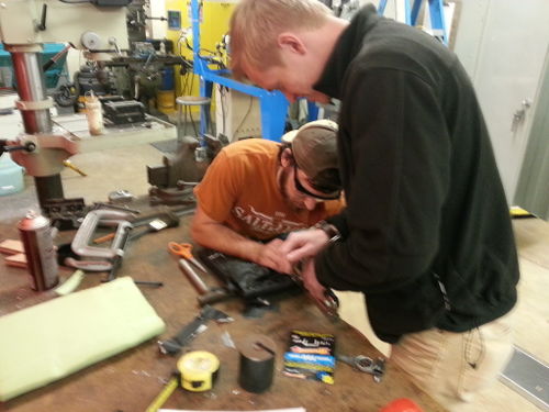
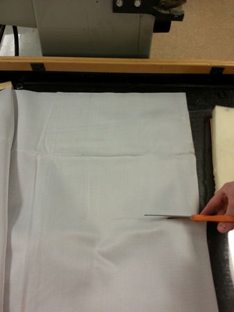
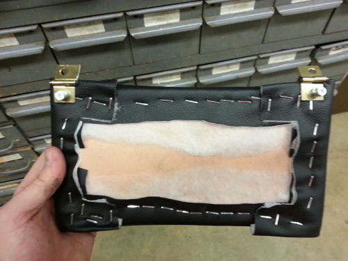
Riley and Will stapling the leather back onto the boards
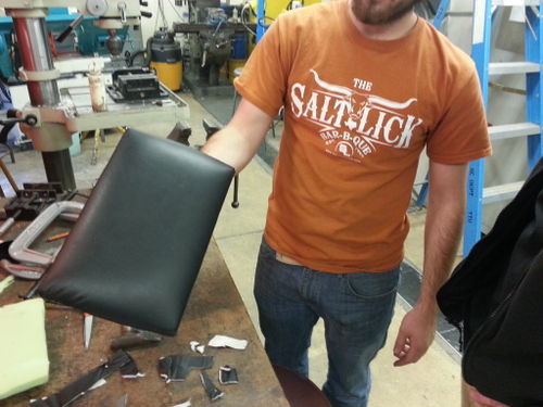
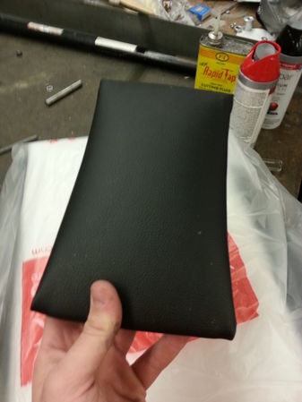
The finished product: foot rest cushions
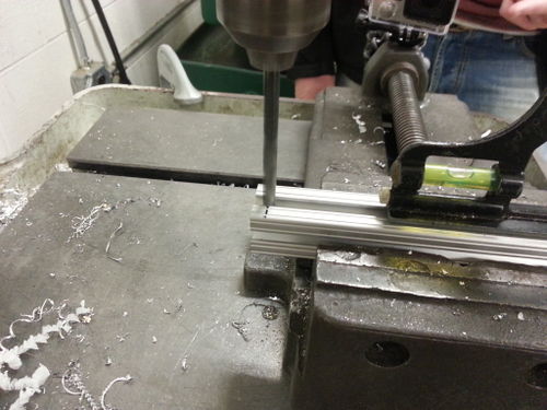
Drilling holes into the T-slotted aluminum tubing that our adjustable foot pegs will be mounted to
Will attaching the T-slotted aluminum to the foot rest
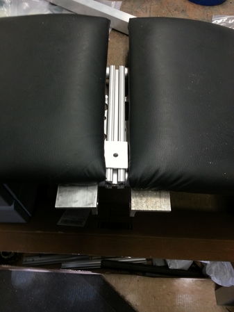
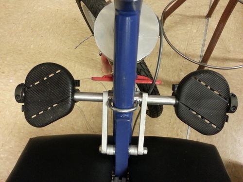
The finished foot rest with the sliding adjustable piece in the middle that our foot pegs will attach to
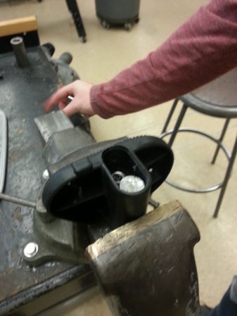
Modifying some foot pedals to go on our foot pegs
Close up of the foot pedals
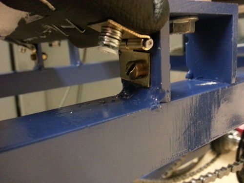
Mounting tabs that our adjustable foot rest will attach to and pivot around via two bolts with cotter pins at the ends
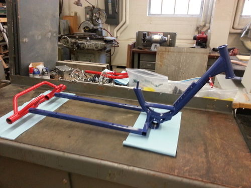
The main part of the frame all painted up
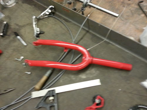
The painted front fork
Using a threaded rod to insert bearings for back axle
Inserting the back axle. Keeping it safe.
Putting the wheels on
Bike with front and back axle mounted
Colt using the persuader to adjust the middle axle
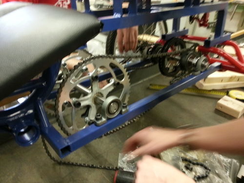
Running chain
Running the figure 8 chain
Aligning the sprockets
Upper frame mounted
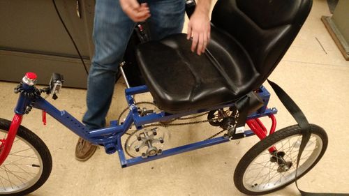
Seat mounted
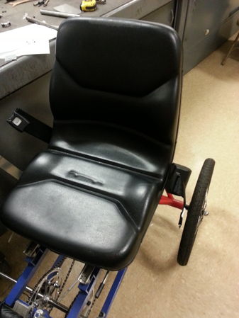
Another view of the mounted seat
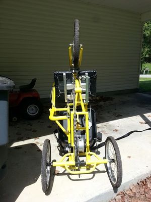
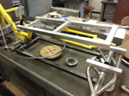
We installed the drivetrain, seat frame, and the seat
Preliminary testing - no brakes or steering
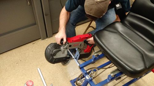
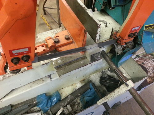
Cutting off the extra shaft with the portaband
The adjustable sliding foot pegs idea did not work, so we are drilling holes into the foot pegs and attaching it to the frame with a U-bolt and two other members
Drilling holes in one of the additional members that will be used in the new foot peg design
The new pedal design mounted to the bike
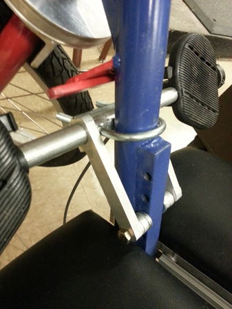
Another view of the foot pedals
The new arm will be fixed to the shaft by welding two shaft collars to the sides of the base of the arm. The shaft will slide through the shaft collars and through a hole at the bottom of the arm
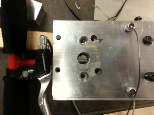
We had to drill new mounting holes into the steering box in order to properly attach the new aluminum arm
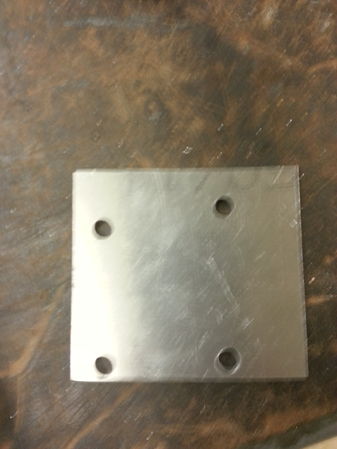
The plate that will be welded to the arm in order to mount the steering box to
Beginning the upholstery of the additional cushioned leg rest
Finished additional leg cushion
Riley cutting some hinges in half to use for an additional movable cushion
We mounted hinges to the leg cushion so it will move freely when the front foot rest is moved
Mounting the additional leg rest to the seat frame
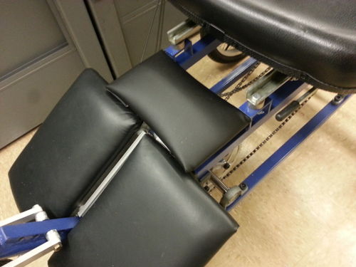
A better view of the mounted additional leg rest
The arm after welding
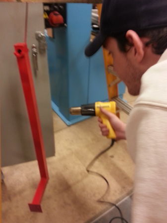
Colt trying to speed along the drying process with a heat gun
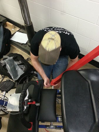
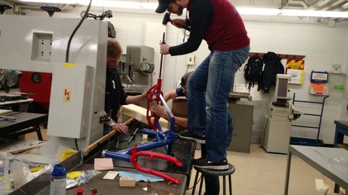
Attaching the arm to the bike
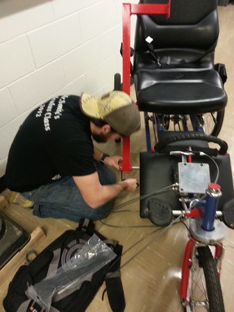
Another view of attaching the arm
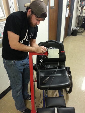
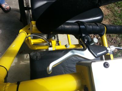
Attaching the steering box/steering wheel to the arm
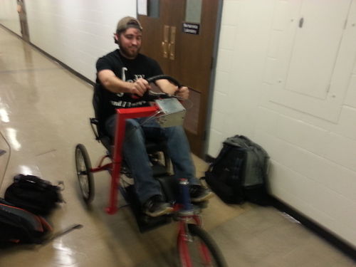
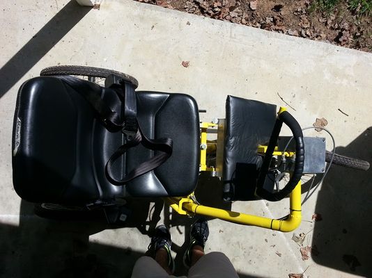
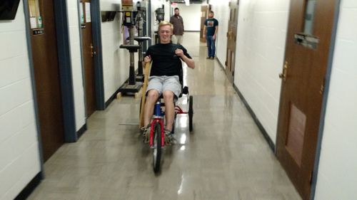
Testing the bike out!
Photos of Completed design
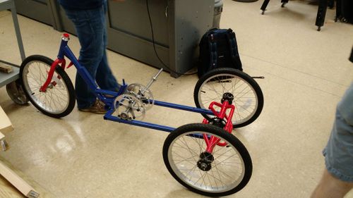
- Final Product
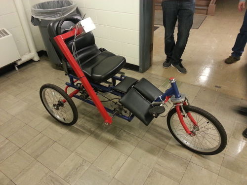
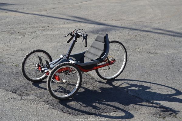
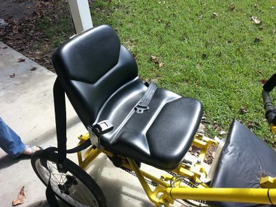
The finished bike!
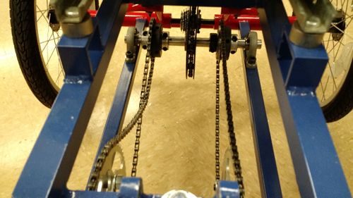
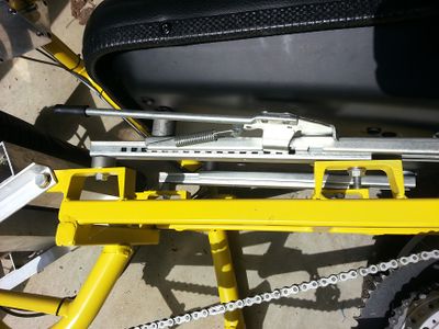
Chain system
Instructions for safe use
Do not use the device unless supervised by an adult that has been fully understood the safe use of this product.
- For ages 12 and up.
- Always fully adjust bicycle to rider size before use.
- Always fasten seatbelt and ensure that extra belt is free of chain system.
- Be knowledgeable of where the hand brake is located and how to use it.
- Never allow hands, feet, clothing, or other accessories to be caught in chain during use. Injury could result.
- Push arm via steering wheel forward and backward to accelerate forward.
- Steer the bike left or right by turning the steering wheel left or right.
- Always maintain a safe speed while using bicycle.
- Use of a helmet is recommended for safe use.
Summary and Conclusions
Overall the project was a success. The bike effectively met the need and the students at Cookeville High School loved the bike.