Assisted-drive bicycle S13
Contents
|
Project Concept
This project is a modified bike design intended to assist the rider with stabilization and power generation.
Team Members
Tommy Hazelwood, Dhruv Patel and Matthew Middleton (Captain)
Introduction
The intended customer of this bike is a fifteen year old girl who suffers from a condition which weakens her strength and mobility. Unfortunately, she is unable to operate a conventional bike safely. Despite her impediments, she still wishes to be able to ride a bicycle on her own. For this to be possible a bicycle must be modified to assist her with stabilization and power generation. She would like the final product to resemble a conventional bicycle as closely as possible while still providing the necessary accommodations.
Design Specifications
The customer is an average height and weight 15 year old female. She will require an adult sized frame which will be capable of supporting up to 200lbs of weight as a safety parameter. Due to limited strength she will need a drive assistance mechanism to aid in power generation. However, she would like to retain the capability of pedaling as an alternative method of mobility. Therefore, the bicycle will possess a conventional drive train as well as a motorized drive. The assisted drive must be limited to a top speed of 10-15 mph as a safety measure. The seat must provide more back support and stability than a conventional bike seat. Additionally, some form of safety belt is required to secure the rider in the seat. The pedals will need to be equipped with straps to help the rider keep her feet in place.
Conceptual Design
There are two primary design aspects, overall stabilization and power assistance, which are each relatively independent of each other. In addition, the rider's weakness will create issues of stability requiring further modifications for the seat and pedals. One method of stabilization would be a form of training wheels scaled up to suit the size of the bicycle. Two prefabricated options were discovered; one with a fully rigid body and one with a spring loaded suspension. Substituting a tricycle frame for the bicycle frame would be an alternative option to the training wheels. With regard to the power assistance, multiple manufacturers offer different forms of electric motorization. Electric motorization would be preferred over other forms of motorization because of simplicity and aesthetics as well as proven efficacy. A motor will be chosen based on price, motor power and battery size. There are many different options of prefabricated strapped pedals available for reasonable prices. Because the threading is universal, any pedals chosen to be suitable for the rider will be compatible with the crank. There are some prefabricated seats available that provide lower back support and include a lap belt. However, if the design permits more side to side movement the seat will have to secure the rider up to the shoulders. This will require a custom seat fabrication and shoulder straps in addition to the lap belt.
Design Concept 1: Motorized Bicycle with Suspension Stabilizers
An appropriately sized bicycle frame will be retrofitted with a spring loaded form of training wheels and an electric hub motor. They offer stabilization with resistance to tipping while still permitting a range of mobility for leaning while turning. The pedals will be equipped with straps to maintain foot placement. Because of the heightened mobility, the seat will be required support the rider up to her shoulders. Also, shoulder straps will be required in addition to the lap belt to adequately secure the rider when leaning.
Design Concept 2: Motorized Bicycle with Rigid Stabilizers
An appropriately sized bicycle frame will be retrofitted with rigid training wheels and an electric hub motor. The rigid supports will provide a high level of stability resulting in more relaxed means of securing the rider. Thus, the prefabricated seat which offers lower back support and a lap belt would be sufficient. The pedals will be equipped with straps to maintain foot placement.
Design Concept 3: Motorized Tricycle
An adequately sized tricycle frame will be chosen to accomplish the stabilization required and retrofitted with an electric hub motor. The tricycle frame will be stable enough to utilize the prefabricated seat for lower back support and lap belt for security. The pedals will be equipped with straps to maintain foot placement.
Concept Evaluation and Selection
A categorical scoring comparison was employed to decide which concept we would proceed with.
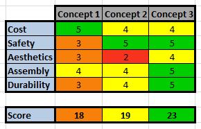
The third design concept far exceeded the other two concepts.
Detailed Design
This section will describe a detailed design process
Description of selected design
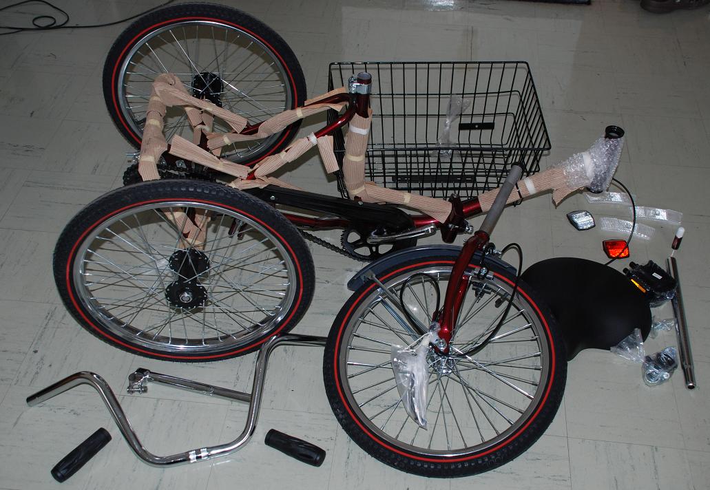
Motorized Tricycle
Detailed description of selected design
♦ Stabilization
Due to the customer's inability to maintain balance independently a tricycle frame was chosen to provide stabilization. The tricycle is a well-designed, sleek method of stabilizing the rider. It requires no effort from the rider to maintain balance but still permits safe turning at reasonable speeds.
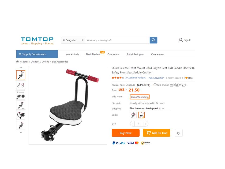
♦ Rider Specific Accommodations
Because of the high stability of the tricycle frame, a less elaborate seat and harness combination were required. The seat is a cushioned, bucket-style seat with a lap belt to secure the rider. In addition, the pedals are equipped with straps to ensure the rider's feet remain in place.
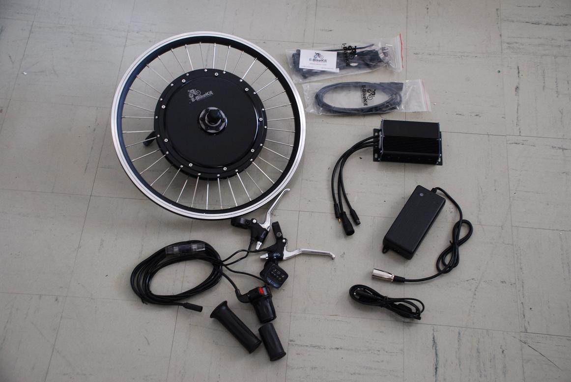
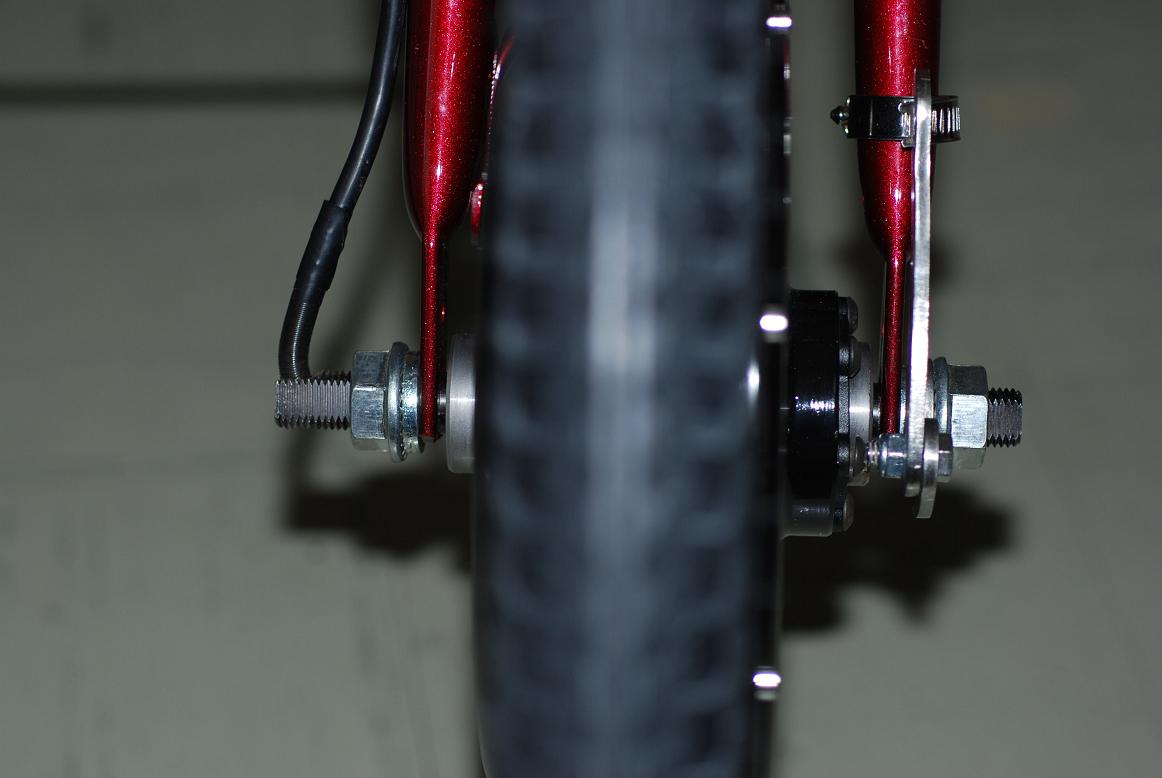
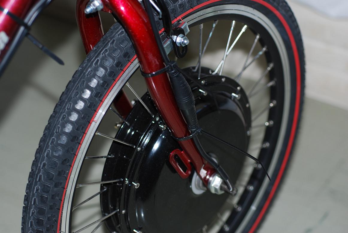
♦ Motorization
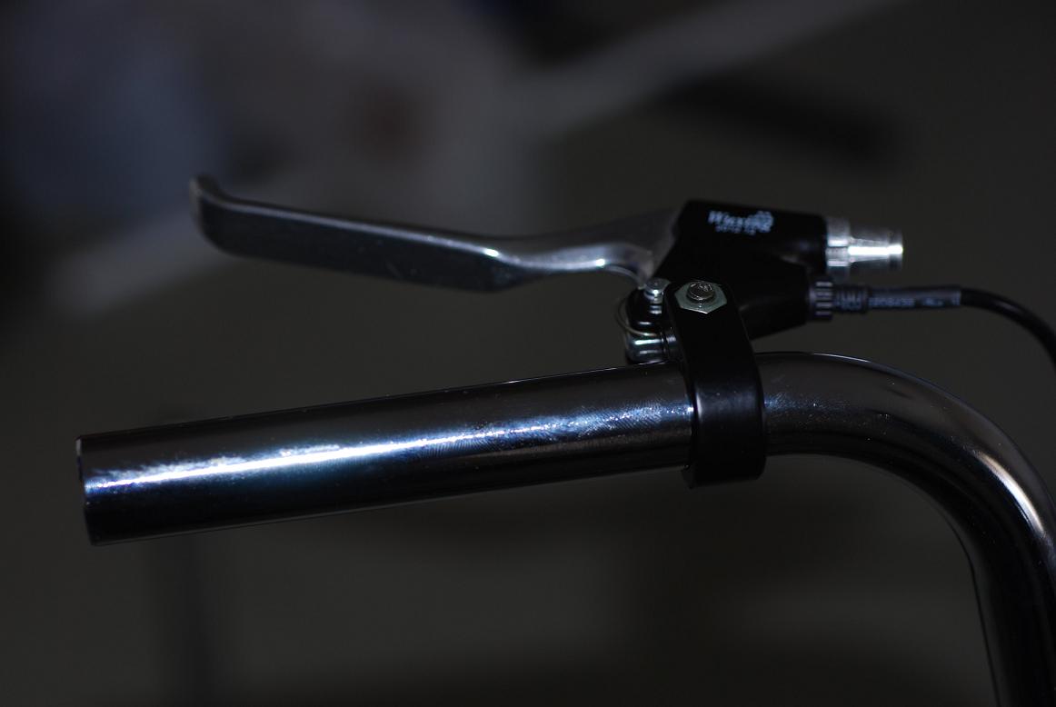
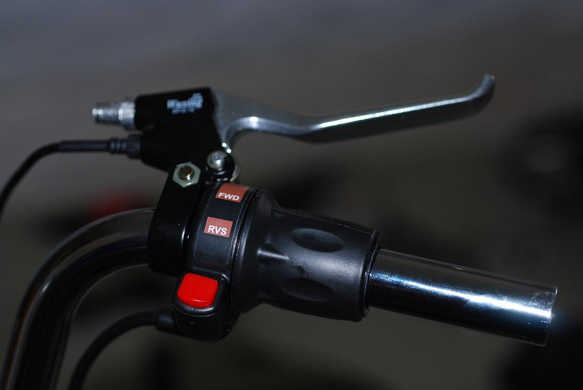
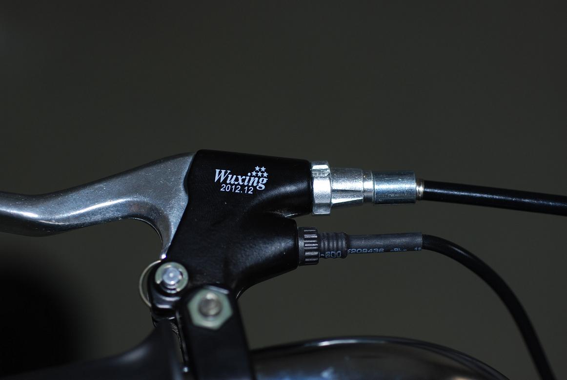
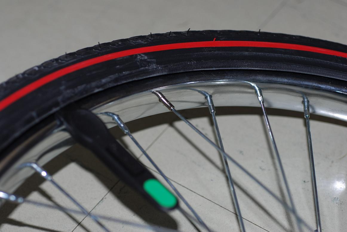
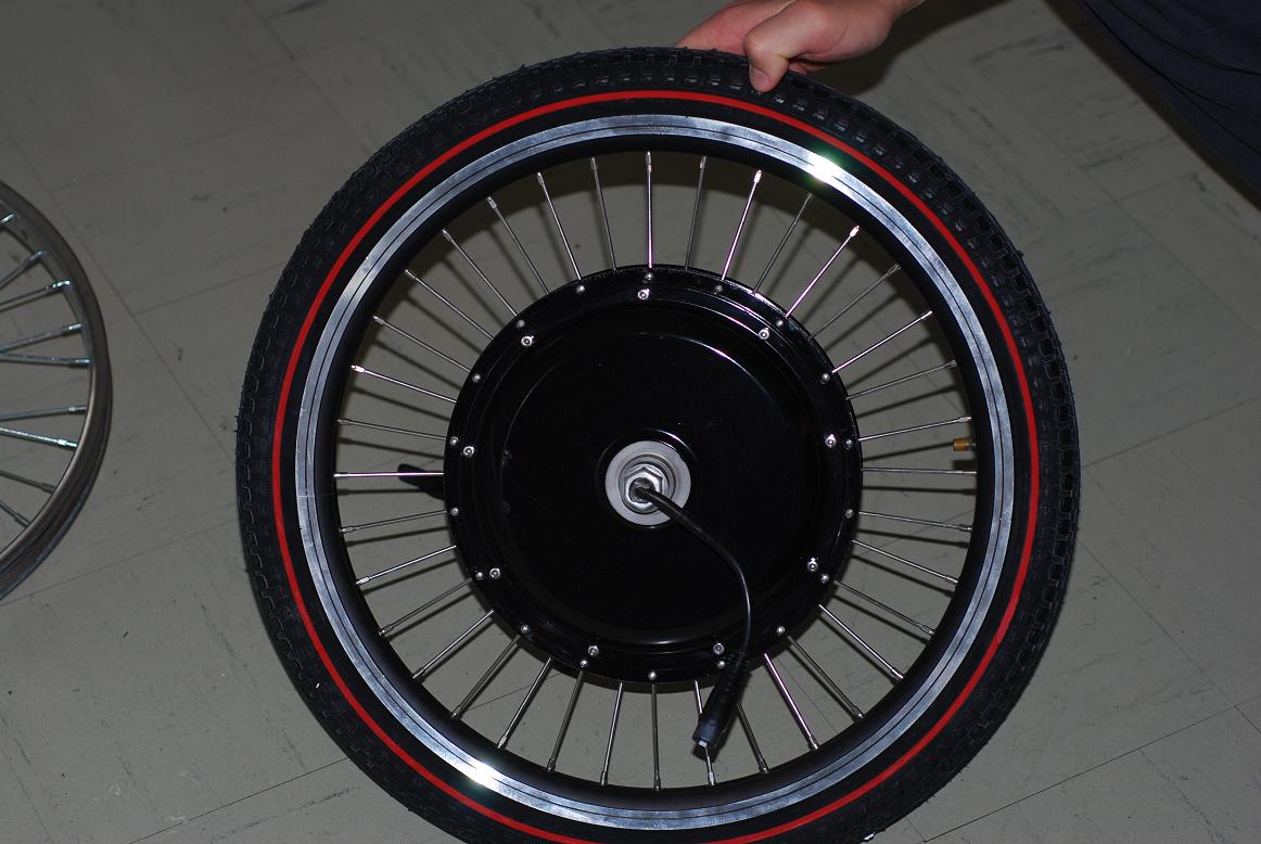
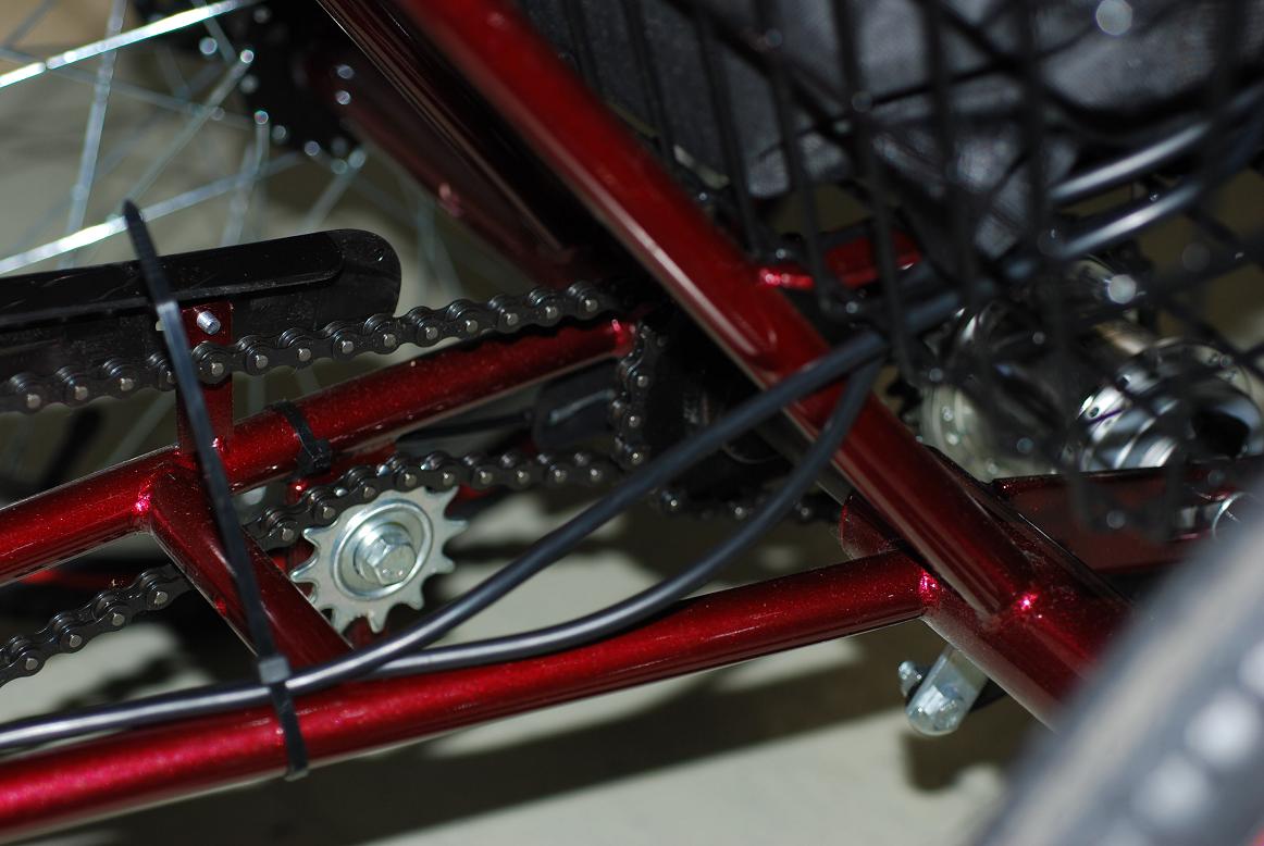
Though a conventional drive train still exists on the vehicle as requested by the customer, an electric hub motor is to be installed in the front wheel. The motor is powered by a battery, secured in the basket on the rear of the tricycle, and will be controlled by a thumb lever throttle. The motor is limited to 10 mph top speed but is also capable of driving in reverse at up to 3 mph.
Analysis Concepts
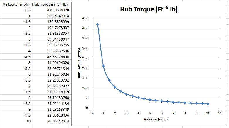
We analyzed the tipping moment of the tricycle with the rider mounted to determine the maximum allowable force, charted the allowable speeds vs. turning radii which can be safely achieved and calculated the torque output by the 500 watt motor at speeds from 0-10mph.
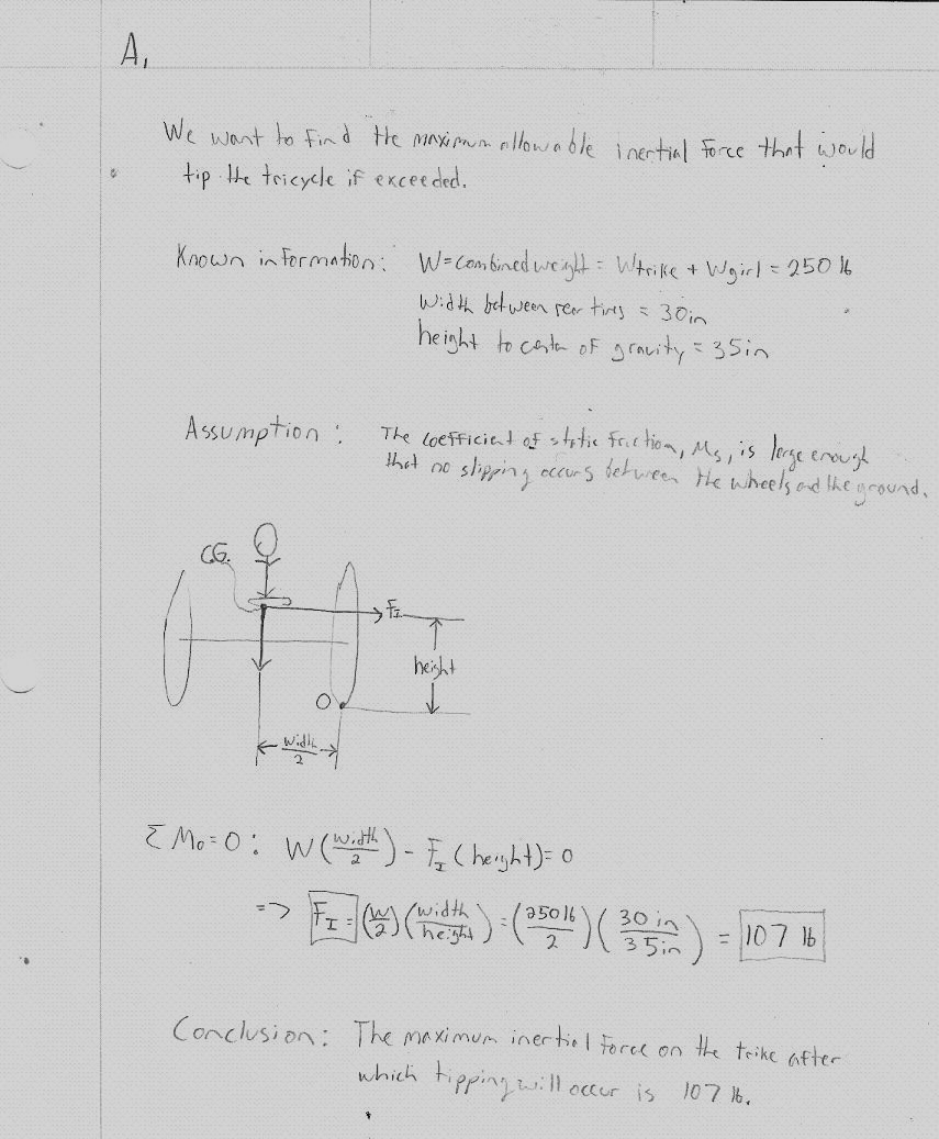
Engineering analysis 1: Tipping Moment
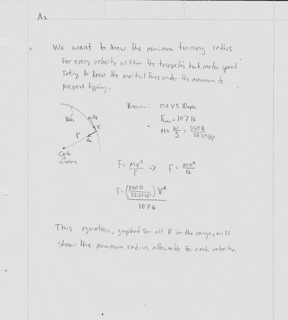
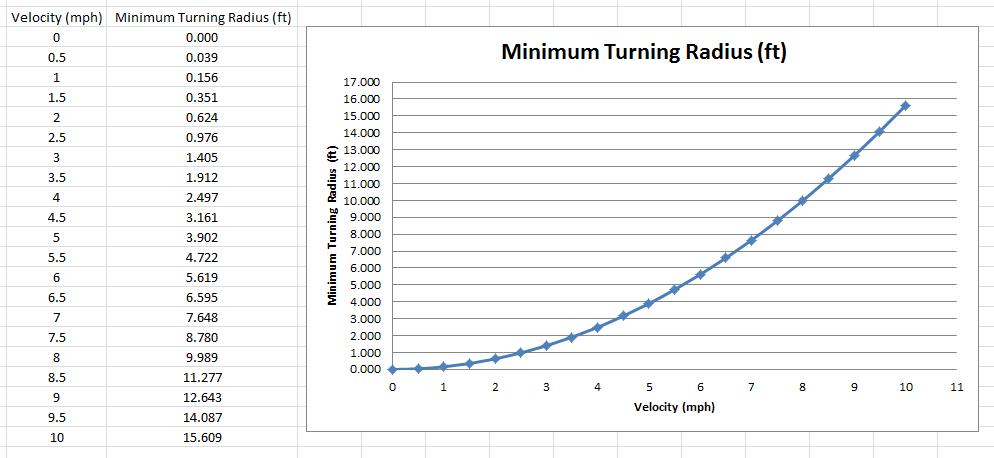
Engineering analysis 2: Turning Radius-Speed Comparison
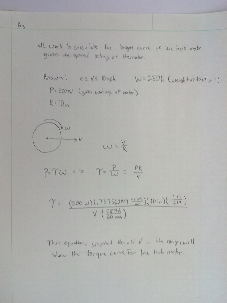
Engineering analysis 3: Torque-Speed Analysis
CAD Drawings
Bill of Materials

Assembly Instructions
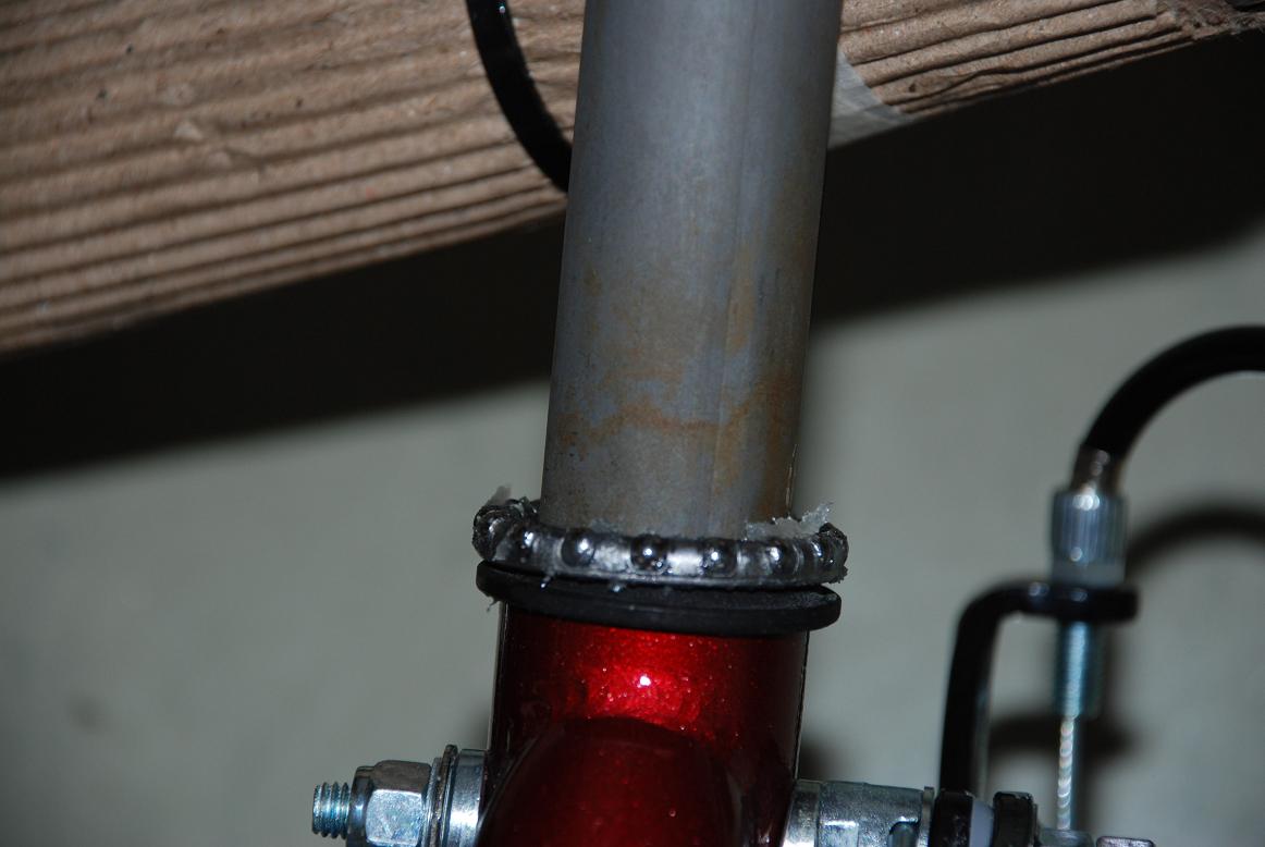
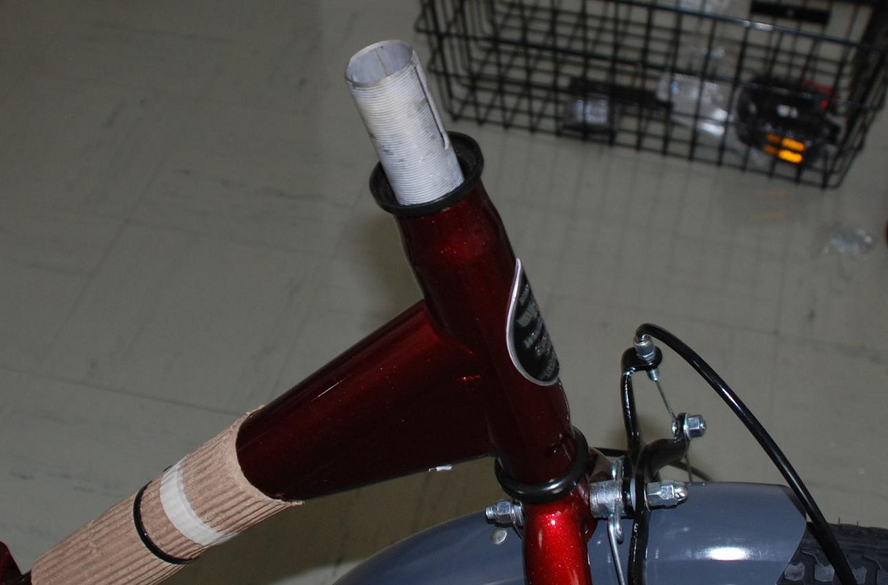
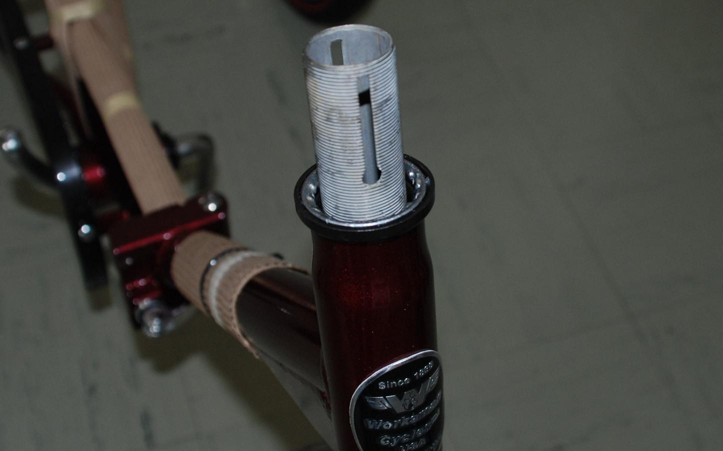
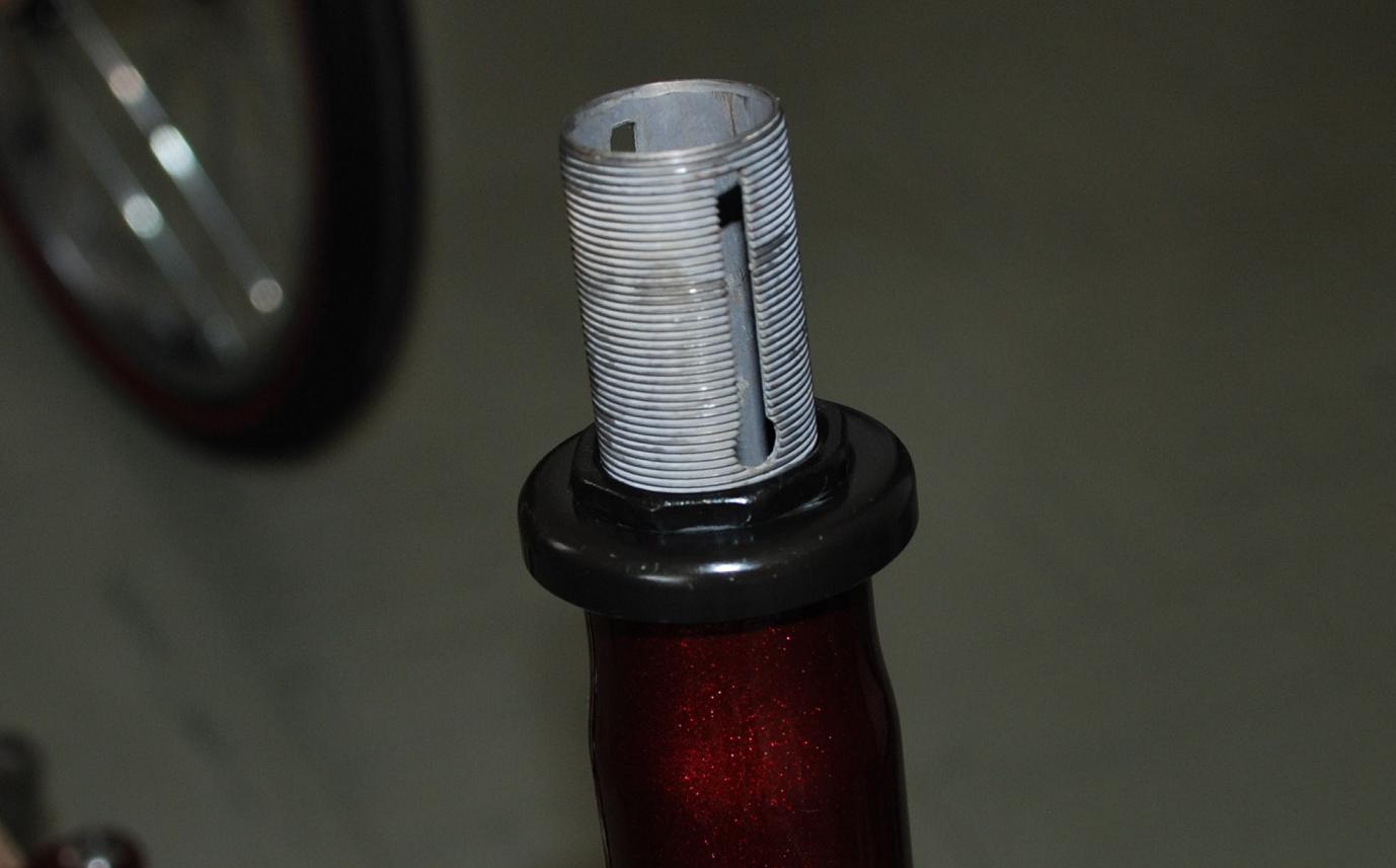
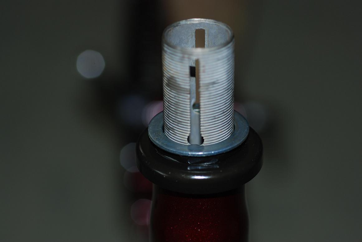
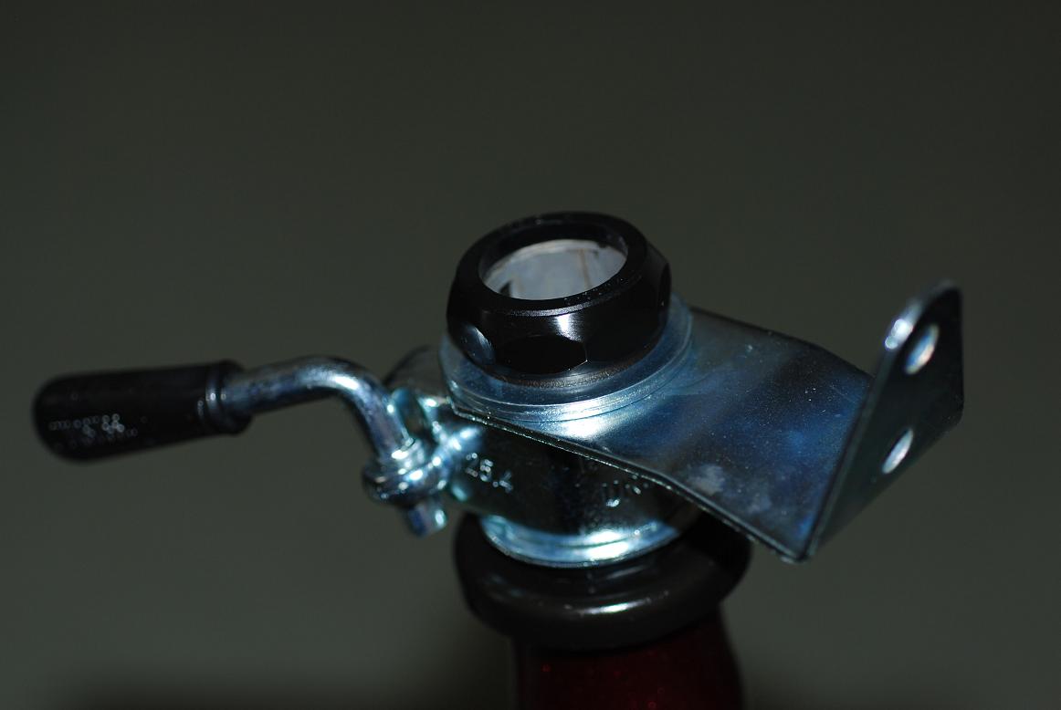
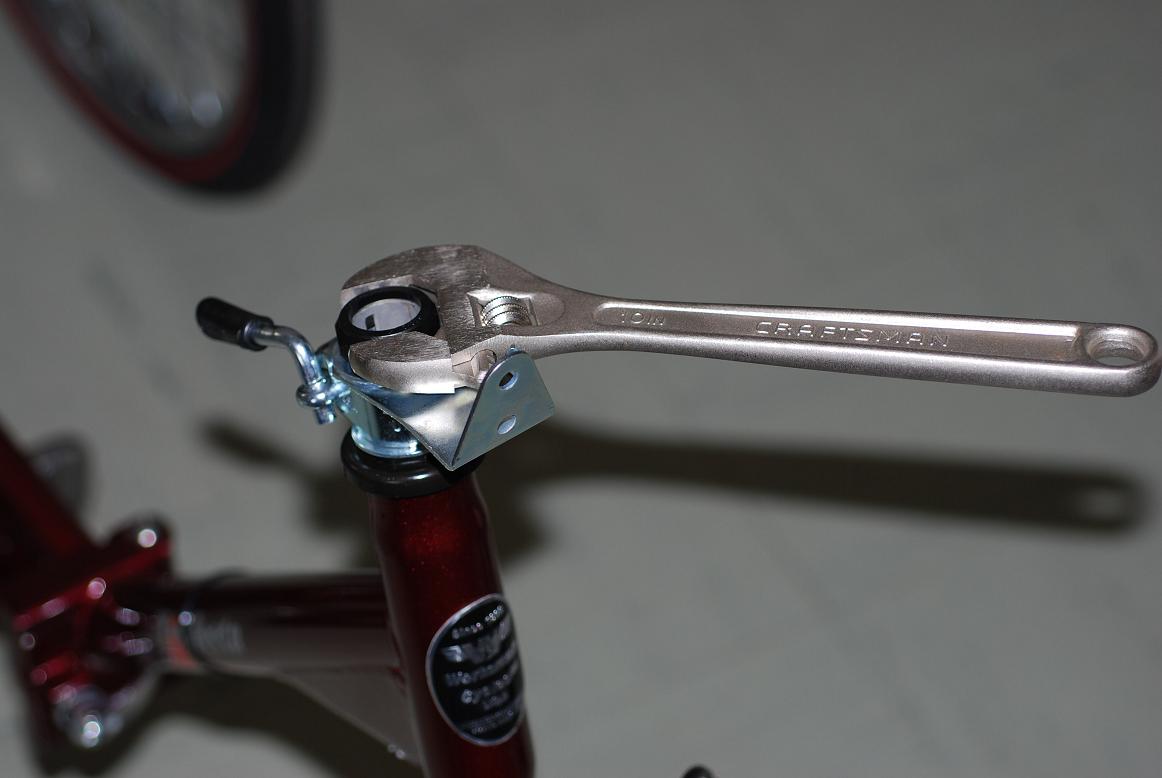
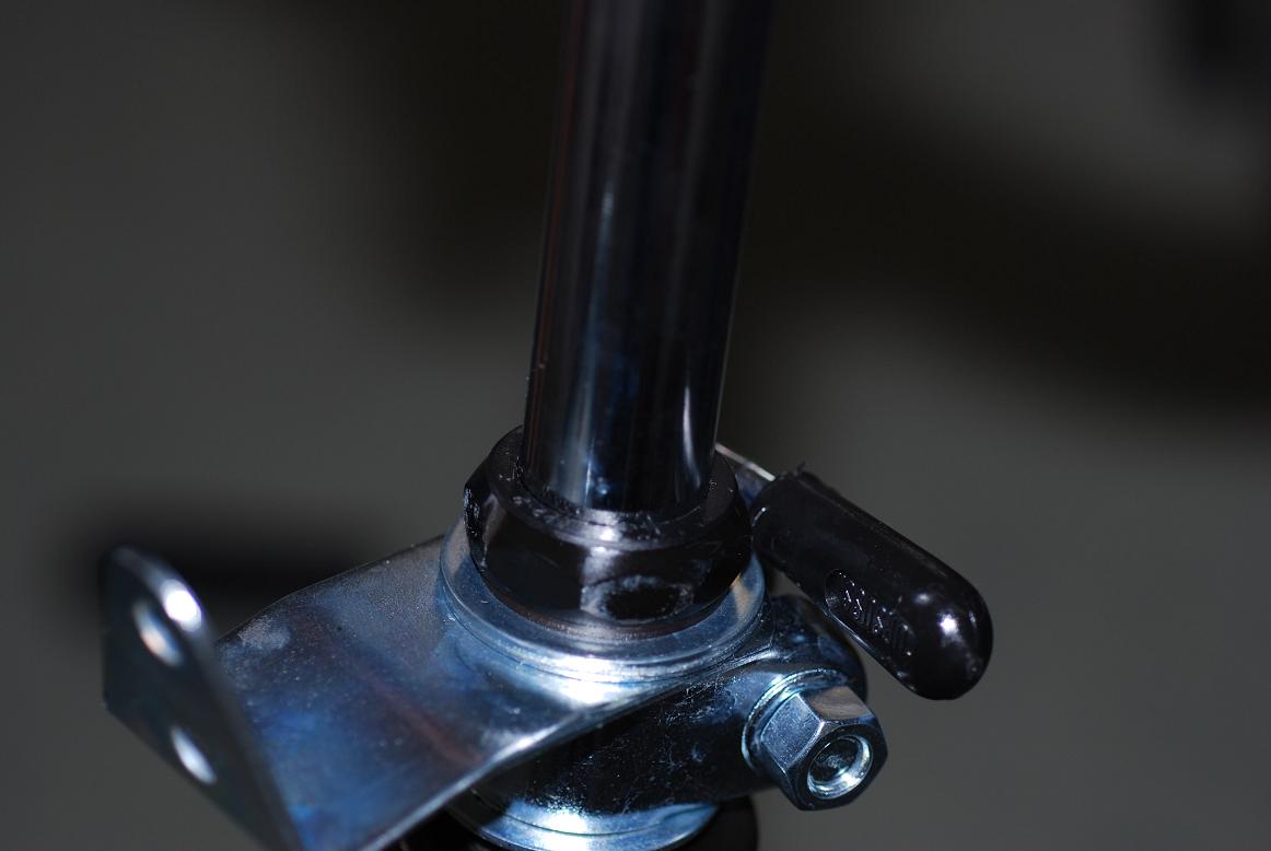
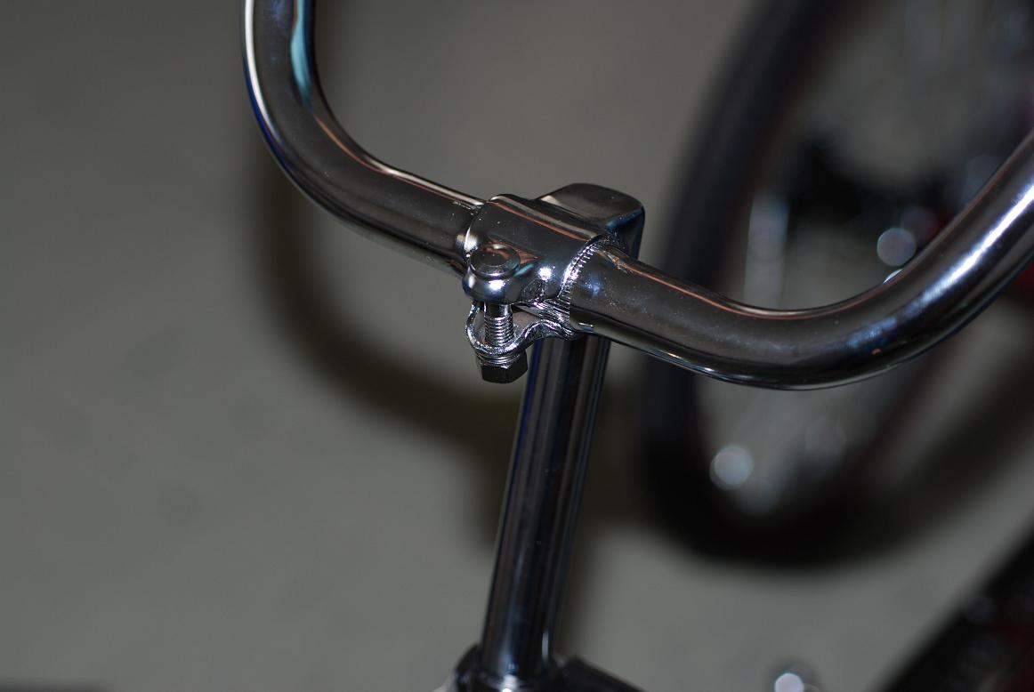


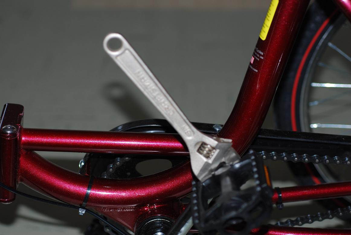
Fabrication Process
Insert pictures of fabrication process
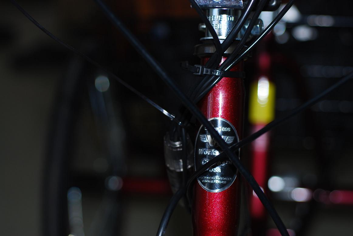
Completed design
Insert pictures of the final product