Assistive climbing rock wall 3
Abstract
- Statement of the need
- - Rene wanted to help children with physical limitations be able to exercise; She needed to add specifically designed equipment such as an assistive climbing rock wall to her indoor playground to further the children's abilities.
- Findings of the projects
- Project outcome
Team members
- ACRW3 (Assistive Climbing Rock Wall 3)
- * Andrew Doyka
- * Austin Garrabrant
- * Hunter Harris
- * Lucas Houge

ACRW3 Team Members: (left to right) Austin Garrabrant, Lucas Houge, Hunter Harris, Andrew Doyka
External Assistance
- Scott Hill
Problem Statement/overview of the need
- We were presented an issue in which children with physical limitations needed exercise and physical development. Rene needed to add equipment such as an assistive climbing rock wall to her indoor playground to meet the aforementioned needs of the children. This wall is aimed to help with the development of children ranging from 2 to 5 years old with varying disabilities.
Design Specifications
List of design specifications. Some of these must be quantitative and measurable. You should be able to use these to compare design options.
1.) A climbing rock wall in her playground area
2.) Space restrictions; must fit in existing area and not take up room for other equipment
3.) 2-5 year old children will be using this wall
4.) Must be kid friendly and motivational so the kids want to use it
5.) Different difficulty and size for varying children
6.) Jungle theme continuation would be a plus
7.) Take up less than 4 feet in width.
8.) Not so tall that workers cannot help or reach top. Set top at roughly 5 feet
Background research
Rock walls can be found in many places and for many uses, but from research there was no wall specifically for disabled children. Rock walls are common on playgrounds for children and there are even disabled rock climbers, but nothing to bridge the gap between. Consumers can purchase and/or build their own rock walls, go to indoor rock wall gyms, or even go to a natural "rock wall." Rock walls for children are a great way to have fun while the child exceresises and works on muscle development. For disabled children the same idea remains but the wall must be adapted to meet the physical disabilities of the child.
Conceptual Design
We came up with many ideas as they are listed below but the driving force behind our ideas were simple ways to help physically disabled children gain muscle movement and strength while having the fun of climbing a rock wall.
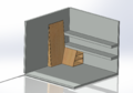
Design Concept 1
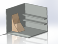
- Our first design was to utilize the corner of the playground area to minimize space taken. This rock wall would utilize the corner shelving unit to have a smaller, easier wall for younger children and then the other portion would be a larger, more difficult wall for more physically capable children. We would like to make clay molds of the children's hands to determine an average size, and then use a 3D scanner to create a virtual model of the clay forms. This virtual representation could then be printed on a 3D printer to generate usable handholds, or to print molds that would allow us to injection mold our handholds. In order to regain space under the existing shelves at the end of the room, storage shelves could be built into the back of the smaller wall. For the larger wall, we would like to create a safety system that would harness the child but allow them to "free climb" to develop physical strength. The smaller wall (only about 3 feet tall) would be designed so that a worker could assist the child up the wall.
Harness system
Design Concept 1 - Rev A
- This design holds the same build out as the Design Concept 1, but the revision comes from a new style of handholds. Both 3D printing and injection molding represent tremendous time requirements. Accounting for possible time constraints in our build time, the wall itself would have slots cut out for handhelds with foam padding for comfort and safety rather than printed or molded handhelds.
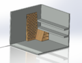
Design Concept 2
- Our second design was to create the two varying rock walls parallel to each other and against the far wall of the playground, again in the sake of space. This design flows from the first design with the 3D scanned and printed/molded handhelds but the two walls with varying difficulty will be next to each other instead of in a corner space. On this design we would like to create or purchase a safety system that would harness the child but allow them to "free climb" to develop the physical strength desired. NOTE: REV A can be applied to this design as well which would adapt the slots cut into the wall directly for handhelds.
Harness system
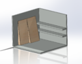
Design Concept 3
- On the 3rd design concept we wanted to have a more "all in one unit" in which the walls would be progressive. The safety system on this design would utilize a single harness system that could extend out over both levels of the wall. We again feel that utilizing the on campus technology of 3D scanners and printers is a good option for our handhelds along with the cut out style as well.
Harness system
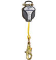
Design Concept 4
- On the 4th design concept we tried to make the most compact, adjustable unit possible by allowing many inclination level settings all in one unit. We also would like to design this unit to be foldable so that it could be easily stored away when not in use. Consequently, it would also be easy for any employee to set up for use. A harness system, like all other designs above, would be adapted to safely support the child but allow free climb to maximize muscle development. A harness system we found that would suit our needs is a DBI SALA Talon 8ft self retracting lifeline. This unit has 8 ft of movement and can handle 310 pounds. The Talon is a compact unit and only weighs 3 pounds with many different attachments making it versatile for whatever harness is used.
Harness system
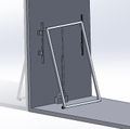
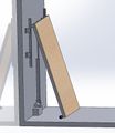
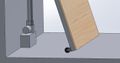
Design Concept 5
- Our last concept we came up with was our favorite and quite frankly the most different from all the others. In this design we would utilize a 24" stroke electric linear actuator to move the wall up and down thus having many angle adjustments to best meet the needs of each individual patient. The actuator has a remote control for easy use. The actuator will be mounted vertically moving the top of the wall up and down the wall mounts while the bottom of the rock wall will be mounted on rollers to allow the bottom of the rock wall to easily move on the floor. As the rock wall is lowered from its storage position (closest to the wall) the top of the wall will descend down the tracks and the bottom of the rock wall will roll away from the wall. For safety we want to attach via VELCRO a padded mat on the bottom side of the frame. Also with safety there will be a "curtain" of sorts to keep children away from the tracks and actuator that will easily fold and stretch as the system moves. When not in use this mat can easily be taken off and stored. The frame itself will be a tig welded aluminum frame with a wood "face." This wooden face will be the wall itself, and to keep the jungle theme going it will be stained a dark brown to reflect trees. The handhelds which will be completely 3D printed will range in colors from green to yellow, red and blue. The tracks mentioned above will be much like a garage door roller track to stabilize and support the frame as well.
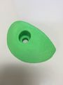
This is an example of the handhelds that will be utilized.
Evaluate concepts/select candidate
| Safety | Adjustment | User Friendly | Cost | Package Size | Final Score | |
|---|---|---|---|---|---|---|
| Concept 1/1A | 5 | 3 | 7 | 8 | 5 | 28 |
| Concept 2 | 5 | 3 | 6 | 8 | 3 | 25 |
| Concept 3 | 6 | 3 | 8 | 8 | 3 | 28 |
| Concept 4 | 5 | 7 | 8 | 7 | 7 | 34 |
| Concept 5 | 7 | 9 | 9 | 7 | 8 | 40 |
Each categories score is based on a 0-10 scale. Final score is out of 50 possible points.
As the above decision table shows, Concept 5 will progress to the next stages.
Detailed Design
Description of selected design
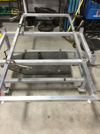
The final design we selected to move forward with was Concept 5 as mentioned above in our decision matrix. This design will utilize a electric linear actuator to move the rock wall through tracks that will allow the wall to be precisely adjusted to a certain angle for the child to use for not only fun but for muscle movement and development.
Detailed description of selected design
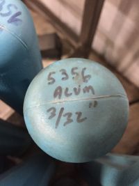
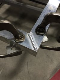
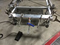
This design is the most adjustable and compact unit that ACRW3 has come up with. Utilizing the 24" stroke electric linear actuator the wall has a broad range of motion and thus adjust-ability. The linear actuator will be mounted to a raised control box, under the rock wall, housing the DC converter and wires. The actuator will also be secured to the wall for added stability. The Linear actuator has a simple "up" and "down" remote control for ease of use. The "rock wall" itself will be a 6061 aluminum 1.5" box tube chassis with a 3/4" plywood face. The wood face will be stained or painted a darker brown to resemble tree bark with the various colored 3D printed handholds to bring out the jungle theme. The actuator will mount to the chassis via two laser cut aluminum plates and a grade 8 bolt or pin with cotter key. The mounts will also have perpendicular weld-in supports for added strength. A support and linear guide system will resemble a garage door style roller and track system on either side of the rock wall. The rollers themselves will be hard mounted to the rock wall with laser cut aluminum mounting plates and the track system will be hard mounted to the wall with laser cut and press braked mounting plates that can be anchored into the concrete wall. We have a prototype of the handhold printed and we are currently testing the handhold for strength; when finished these will be, like aforementioned, in many colors, shapes, and sizes for a wide variety of options. The material chosen here will be ABS. PLA was ruled out as a material option because it can become brittle over time and is biodegradable. For safety we want to have a VELCRO'd foam pad much like at a gymnastics studio attach to the bottom of the wall and then curtain style enclosures on the side that will move with the wall to block off the inner workings and pinch points of the mechanisms. With the therapist in mind the wall is only 5' tall so that the therapist can follow and help the patient as high as they can go easily within reach.
Analysis
The information we wanted to gain from analysis centered around safety. Force analysis of the system to determine loading throughout the range of the linear actuator and forces on mounting points were focused on.
Engineering analysis 1
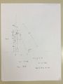
Velocity Analysis
This analysis was done to find the speed at which the rock wall moves horizontally as the linear actuator is moving the top of the wall. It showed that it would take 2 minutes for our wall to go from one extreme position to the another - max slope to min slope.
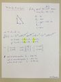
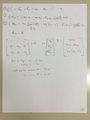
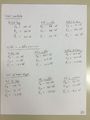
Engineering analysis 2
Caption1
Caption1
Caption1
Caption1
We analyzed our system to figure out what the resultant forces on the rock wall supports. We calculated these forces with the wall in 3 different positions and the kid in 3 different positions. we assumed a 100 pound kid to ensure safety in our calculations This enabled us to ensure the linear actuator, the wheels, and the garage door tracks would not be overloaded. We found that the max load on the garage door tracks would be 8 pounds, distributed through 4 wall mounts. The max force on the wheels will be about 125 pounds, which will be distributed between 2 wheels. The max force on the linear actuator arm will be 115 pounds, and it is rated for 1000 pounds.
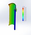
Engineering analysis 3
Roller Track deformation under 50 pounds of load. Max is .0004172 mm ~ .000016 in. This was with the flat side fully fixtured and load applied to the rear contoured wheel track.
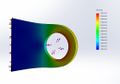
Analysis of the Actuator Frame mounting bracket. 200 pounds of load applied. Max deformation is .0008597 mm ~ .0000338 in. This was with the bottom of the bracket fixtured as if it were welded to the frame and load applied in bolt hole.
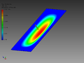
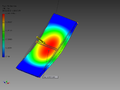
Deformation of the wood being used for the wall itself. A point force of approximately 112 pounds was applied to the center of the 3' by 5' 3/4" pine plywood wall. Max results are shown in the red region at approximately .004"
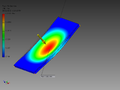
This analysis included not only the pine rock wall but the full 1.5" box 6061 aluminum frame. Max deformation was .0059"
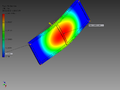
Supplemental view
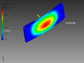
Deformation with an added cross bar at the mid point of the side frame tubes. This reduced max deformation to approximately .003" under the 112 pound load.
________________________________________________________________________________________________________________________________________________________________________________________________________________________
NOTES:
- We found through our analysis that the bottom roller wheels will support the weight of the wall and child but for manufacturing reasoning we are currently sourcing better options. The small diameter of the wheel makes it to where we will have to eliminate mounting holes. That could possibly create an unnecessary moment on the wheel bracket. By finding a better bracket/wheel package we will have better mounting options and thus a safer more effective rolling system. One other option brought up would be to design an angled mounting plate for the interface between the frame and currently selected casters to utilize the full mounting plate and still allow for full range of motion.
CAD Drawings
Insert drawings of all parts and the assembly
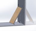
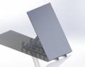
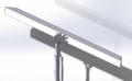
General View of the wall
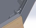
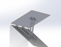
Track system for stabilization and load transfer
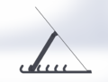
View of system without rockwall attached to show linear actuator
View of the box that will get linear actuator off of ground and house DC converter
Casters will be modified to work on our system for easy rolling on flooring
- Note: No pictures show the foam pad that will be VELCRO attached for a cushion in case of a fall; Also there will be a curtain of sorts that will go on both sides of the wall to cover up the inner working of the wall for aesthetics and safety reasons.
Bill of Materials
| Item No. | Quantity | Part Number | Source | Description | Price |
|---|---|---|---|---|---|
| 1 | 1 piece | FA-1000-L-12-24" | Firgelli Automations | Linear Actuator | $219.99 (purchased) |
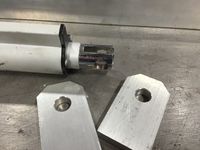
| 2 | 2 pieces | ACRW3-001 | LDI | Actuator Frame Mount | RFQ out |
| 3 | 4 pieces | ACRW3-002 | LDI | Actuator Frame Mount Support | RFQ out |
| 4 | 2 pieces | ACRW3-003 | Ryerson/KGS/TDS/Loftis | 3' Frame Tube (1.5" box) | RFQ out |
| 5 | 2 pieces | ACRW3-004 | Ryerson/KGS/TDS/Loftis | 5' Frame Tube (1.5" box) | RFQ out |
| 6 | 1 piece | ACRW3-005 | Custom | Base/Mounting Box | Varies |
| 7 | 2 pieces | 78155T630 | McMaster-Carr | Wheels | $3.96/each |
| 8 | 1 piece | ACRW-006 | Home Depot/Lowes | Rock Wall | ~$50 |
| 9 | 4 pieces | ACRW3-007 | LDI | Wall/Track Brace | RFQ out |
| 10 | 2 pieces | Currently Sourcing | Roller Track/Wheels | Currently Sourcing | |
| 11 | 2 Pieces | ACRW3-008 | LDI | Wheel Brace | RFQ out |
| 12 | 50+ pieces | ACRW3-009/010/011 | TTU iCube | Handholds | Free |
Assembly Instructions
Fabrication Process
Testing and implementation
Describe testing, delivery, how used/received by the family
Photos of Completed design
Insert pictures of the final product
Instructions for safe use
Provide a clear summary of safe use for the family. Do not use the device unless supervised by an adult that has been fully understood the safe use of this product.