Bat Trike
Abstract
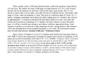
This project is an attempt to build a tricycle for children with visual impairment. This vehicle is being created to fill two main functions. The first function is to give visually challenged children the ability to experience the joy of riding a tricycle. The second function is to introduce a fun and easily accessible method for visually impaired children to exercise with.
Team members

From Left to Right::
- Thomas Bannister
- Allysun Hatton
- Michael Roberts
- Ian Gwaltney
- Curtis Sickmiller
Special Thanks to:
- Dr. Canfield - for providing the team with this opportunity.
Problem Statement/overview of the need
- Problem Statement: Build a tricycle for visually impaired children. The tricycle should focus on obstacle avoidance.
- Overview of Need: Visually impaired children lack out on certain experiences. This project attempts to correct one of these missed experiences by allowing visually disabled children to enjoy the freedom of cycling. Along with giving children the joy of riding a tricycle, the "Bat-Trike" also serves a more practical purpose. Cycling is a great exercise for all ages. It promotes muscle building, increases stamina, and improves cardio-vascular fitness. A tricycle is a fun and easy way to promote exercise in young children. In order to accomplish the task of allowing a visually impaired child to freely ride, the tricycle will need to help the child with obstacle avoidance.
Design Specifications
1. Cost - The system would hopefully be relatively cheap, allowing it to be picked up by any wanting family.
2. Reliability - The system should, above all, be reliable. If the system fails in any major ways it could harm a child.
3. Ease of Use - The system should not take a master's degree to employ. The product should be fairly simple for a customer to install and use.
Background research
As far as the students are able to tell, there are no current items on the market that fit this need. This means there is a large gap in the market that this product could fill.
Conceptual Design
The conceptual design process consisted of each member doing research on the project outside of the group. The students then came together to create three possible design concepts.
Design Concept 1
Lidar
This system would employ Lidar to avoid objects. Much like how smart card avoid objects, the bike would look for objects in its path using lidar. When it finds something it will alert the child to begin turning.
We believe this design would work well. However, it would be rather expensive. This isn't necessarily a good design because it breaks our design goal of cheap. However, it would probably be more reliable than sonar.
Design Concept 2
Sonar
This design takes into affect a bat-like approach to object detection. Sonar sensors would be installed on the trike in such a way that they create a field in front and to the sides of the trike. When an object gets in the way, cones on the trike will pick up the returning sound. From there the bike will alert the user which direction they should turn.
The team estimates that this idea would work some of the time. The current fear is that the sonar waves could be absorbed by a surface, leaving a blind spot in the object avoidance. This would cause a child to unknowingly slam into a object.
Design Concept 3
Grid
This system focuses less on object avoidance and more on the free ride concept. The user would place down four sensors that would detect when the child is close to passing them. The bike would then alert the child that they need to change course to avoid Leaging the area.
The team believes this idea would allow the user to freely ride around. However in its current state it does not take on the task of object avoidance but instead bypasses entirely. This is not necessarily a bad or good design.
Evaluate concepts/select candidate
Originally the group decided they wanted to employ the Lidar option. However,after discussing the possible design concepts with Dr. Canfield, the group settled on a design not detailed above. The new design will use a combination of long and short range finders to build an occupancy grid. This occupancy grid will be able to detect objects in the path of the trike, and will alert the user through some sort of feed back.
Detailed Design
Description of selected design
On a suggestion from Dr. Canfield we chose to use range finders instead of our original concepts. The range finders will be arranged in a circular array attached to a stepper motor, which will allow the array to scan the area around it.
We chose the Arduino Mega2560 as the controller for our system due to the amount of analog i/o pins it contains. To prevent damage, the Arduino and the motor will be contained in a 3D printed casing below the array. The casing will have adjustable zip ties to allow it to be attached to the the trike. The method of feedback is currently undecided between a haptic or sound based system as we are awaiting input from the sponsor and James Brown, the president of the National Federation of the Blind Tennessee.
Detailed description of selected design
- Casing: 3D printed ABS plastic was chosen due to its durability and strength. 3D printing the chassis also gives us the ability to create a container that matches our exact specifications.
- Programing Platform: The Arduino Mega2560 was chosen due to it’s easy-to-use software, fast processing speed, and large amount of analog inputs that will be used with the range finders. The Arduino software also contains a vast amount of ready made open source code and functions that can be used in our application.
- Sensors: The Sharp GP2Y0A710K0F is our long range range finder. It can read distances from 100 to 550 cm, which gives us a large field of view. For objects within 100 cm we have chosen the Sharp GP2Y0A02YK0F that can read from 15 to 150 cm. Between the two sensor types we can cover a large area of view allowing the user plenty of warning on upcoming objects. We will be using the sensors to build an occupancy grid.
- Stepper Motor: Though originally we considered servo motors, we discarded them in favor of a stepper motor for its high accuracy and reliability. We have chosen the SY28STH32-0674A stepper motor. This is a NEMA-11 bipolar stepper motor with a 1.8 degree step angle and 600 g-cm holding torque.
- Motor Controller: To control our stepper motor we chose the Sparkfun Easy Driver due to it having an acceptable voltage and amps output for our motor. The Easy Driver is a breakout board for the A3967 microstepping driver chip.
- Battery: The battery we chose is the Teenergy 7.2V 5A rechargeable battery. The battery was chosen for its small size while still being able to supply the power needed to run our system.
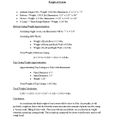
Analysis
We decided on four engineering analysis. These are: Material Selection, Pivot and Scan Information, Weight of System, and the Electrical Needs of the System.
Material Selection

Material Selection 1

Material Selection 2
Material Selection 3
Pivot and Scan Information
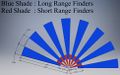
Visualization of Range Finder Spread
Explanation
Weight of System
Weight Calculations
Electrical Needs of System
Electrical Calculations
CAD Drawings
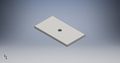
Top of Original Casing
Bottom of Original Casing
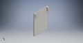
Front Wall of Original Casing

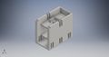
Assembly of Original Casing
Front of Original Sensor Array
Angled View of Original Sensor Array
Top of Original Sensor Array
Bill of Materials
Original Proposed Bill of Materials
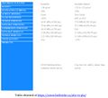
| Quantity | Item | Description | Source | Part Number | Price |
|---|---|---|---|---|---|
| 1 | Arduino Mega2560 | Microcontroller | https://www.arduino.cc/en/Main/ArduinoBoardMega2560 | N/A | $32.95 |
| 1 | Tenergy 7.2V 5Ah Battery and Charger | Battery + Charger | http://www.all-battery.com/TenergySmartUniversalChargerandHighPowerBatteryPackCombo-91104.aspx | N/A | $52.99 |
| 1 | Stepper Motor | Motor | https://www.pololu.com/product/1205 | N/A | $15.95 |
| 7 | Long Range Finder | Long Range Finder | Tennessee Tech | GP2Y0A710K0F | Free |
| 6 | Short Range Finder | Short Range Finder | Tennessee Tech | GP2Y0A02YK0F | Free |
| 5 lbs | ABS Plastic | Casing Material | http://www.amazon.com/HATCHBOX-3D-ABS-1KG1-75-WHT-Filament-Dimensional/dp/B00J0H6NNM/ref=sr_1_3?s=industrial&ie=UTF8&qid=1458530992&sr=1-3 | N/A | $21.98 per 2.2 lbs |
| Varying | Miscellaneous Hardware | Hinges, Latches, Screws, etc. | http://www.mcmaster.com/ | N/A | Varying |
| 1 | H Bridge | Control for Motor | https://www.sparkfun.com/products/12779 | ROB-12779 | $14.95 |
| 1 | Mounting Hub | Attach Casing to Motor | https://www.pololu.com/product/1203 | N/A | $7.49 |
Final Bill of Materials
| Quantity | Item | Description | Source | Part Number | Price |
|---|---|---|---|---|---|
| 9 | Long Range Finder | 1 meter to 8 meter Range Finder | Tennessee Tech | GP2Y0A710K0F | Free |
| N/A | ABS Plastic | Casing Material | Tennessee Tech | N/A | Free |
Assembly Instructions
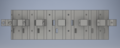
Assembling the range finder array is a rather simple affair. There are two sections to the sensor array: the head and the body. Each section holds a number of range finders within the "gaps" located in the array. The head holds three range finders while the body holds six. Place a 2Y0A710 Sharp Rangefinder in each of the "gaps" in both of the head and body sections. Upon completing that, the head slides into the body using the pegs on the far left and right of the array. This takes care of the hardware portion of the assembly, next comes the wiring portion of the assembly.
Each of the nine range finders has four wires sticking on the back. Reading from left to right the wires represent: ground, signal, power, ground. Connect all ground wires to a common ground, and connect all power wires to the 5 volt power source on the Arduino Due. After ensuring all power and grounds are connected move onto connecting the signal wires. The signal wires need to be connected in a specific way in order for the occupancy grid to work, luckily the order in which they are connected is very straight forward. Turn the front of the sensor array away from you, so that the back of range finders face you. Start with the range finder on the bottom row to the far right. That range finder connects to A0 on the Arduino Due. The range finder on the second row on the far right connects to A1. The range finder on the third row to the far right connects to A2. Now we go to the middle range finder on the bottom row. This range finder connects to A3. Connect the remaining range finders using the same pattern as you have for A0 through A3. Once all is said and done ports A0 through A8 should be connected to the range finders. After this is completed the only remaining step is to upload the provided code to the Arduino Due.
Fabrication Process
Below are photos of the Inventor drawings that ultimately became the sensor array. The photos are in the following order:
- Head
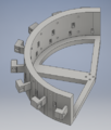
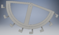
- Body
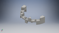
- Full Assembly
Head of the sensor array.

Body of the sensor array.

Full assembly of the sensor array.
The Head and Body were both printed at the IMaker Space in the Tennessee Tech Volpe Library. The pieces were assembled by the team.
Testing and implementation
The team started testing by first determining the distance equations for each range finder. This was necessary for the occupancy grid, as it lets the user know how far away from an object they are. Once each of the range finder equations were found, the team tested the how the distance that output from a range sensor calculation by taking measure steps to and from the sensor. Once the team was happy with their results, they were attached to the sensor array.
In order to test the sensor array the team went to a large open area. They set the device down and then one student would either stand in the way of or walk past the array. Using only the occupancy grid the students attempted to guess what the student had done, along with where they started/were standing at. Once the students were confident they could locate people, they demonstrated the functionality to Dr. Canfield. Here it became evident that the range sensors were outputting a lot of noise. Under Dr. Canfield's suggestion the team added a median filter.
In order to test the median filter, the students added it to a copy of the working occupancy grid code. First they ran the device using the regular code and wrote down distances measured from each range finder. Then they uploaded the code with the median filter and did the same thing. By doing this the team was able to determine that the median filter was working correctly. At this point the team needed to once again test the occupancy grid in order to see if it was possible to navigate with it.
In order to test the feasibility of navigating with the occupancy grid the students took the range sensor to the main floor of Brown. A student from the team would be picked to test the array. That student would close their eyes while the sensor array (located on a wheeled cart) was positioned. The student was then spun around to disorient them, and led to the computer with the occupancy grid on it. A blanket would go over the head of the student and the computer, ensuring that they could not see their surroundings. From here the student was asked to walk to the far end of the hallway. Obstacles, such as people and boxes, would be put in the way of the oncoming student. Three separate students were able to navigate the hallway in this way.
Photos of Completed design
Below is a photo of the completed design. There were a lot of changes that occurred between the original design and the final design. The team was unable to complete the entire project, and instead focused on creating a reliable occupancy grid. There are a total of nine sensors on the sensor array.

Sensor Array as seen from the front.

Sensor Array as seen from the top.
Instructions for safe use
Before running the device ensure that all cables are properly connected. Make sure to keep the microcontroller and sensors away from water. It is highly recommended to have an adult on hand when running the device who can keep an eye out for dangers in the event that the system fails. Do not use the device unless supervised by an adult that has been fully understood the safe use of this product.
Project Summary, Reflection
This was a great learning opportunity for the students, even if they were not able to fully realize the design. The students were able to create an occupancy grid that could be viewed using Matlab. However, the students were unable to implement a feedback system for visually impaired children, and due to this the system is not very portable. This is because in order to read any data coming from the Arduino Due a computer must be attached.
That being said, the occupancy grid does work. The students were able to navigate the main floor of Brown using only the grid. The largest issue found with the current product is that it was designed to be used in a large open area -- not a hallway. Due to the range of the range sensors (1 meter to 8 meters), the changes in the grid are slight as objects approach. This problem could be solved by moving to shorter range finders than the ones currently on there.
In reflection, the students wish they had more time. A large portion of the group (3/5th of it in fact) became bogged down with other responsibilities and therefore did not dedicate as much time as they would of liked. The range finder idea, while cheap, also has a lot of issues. One such issue is the amount of area a single rangefinder can cover. Each range finder can only cover so much area, which relates to about 16 degrees on the occupancy grid. In order to avoid dead spots and reach a full 180 degrees of coverage a lot of range finder need to be employed -- more than what are already being used. Along those same lines, because the range sensors have such a large area they cover, it is difficult to tell where an object is in the field of view. Regardless of whether an object is to the far right, left, or in the center of a range finders field of view, the range finder will read as if the object is dead in front. While not a large problem, it doesn't make it difficult to discern where things are.
For future work the team recommends either employing a back up set of range finders that cover a shorter distance, or moving to a Lidar based system. A feedback system also needs to be employed in order to interact with the occupancy grid in a non-visual way.