Cuntoir
Abstract
The goal of this project was to make a toy of sorts for a child with no lower mobility (requires being in a wheelchair all the time). We recognized that this child would need to develop upper body strength in order to be self sufficient in their wheelchair so we decided to make a toy to help build that upper body strength. Our group constructed a wooden go-kart that is propelled by a four bar mechanism with a lever bolted to the gear sprockets so the kart will move forward by a ratcheting motion. Throughout this project, group learned the importance of details in design and thorough analysis to ensure success.
Team members
Problem Statement/overview of the need
Our group is wanting to target youths who are lacking the upper body strength it takes to propel a wheelchair normally on their own, including, but not limited, to children with cerebral palsy. Being unable to move the wheelchair on their own takes away their sense of independence and can inhibit them from doing things with their friends like they might normally do.
Design Specifications
List of design specifications. Some of these must be quantitative and measurable. You should be able to use these to compare design options.
1. An ideal length for the occupant to easily reach the handle and use the lever.
2. Connection of handle to wheel must sit tightly in place, while also being relatively easy to remove for transportation purposes and to adjust levers with age.
3. Must have brakes.
4. Use of a lighter material (small mass) so it does not add much weight to the wheelchair possibly aluminum.
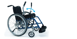
Background research
Two prominent wheelchair propulsion designs are manufactured by RioMobility and NuDrive in Canada.
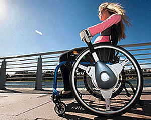
1.) RioMobility
 Design Name: The Pivot
Product Specifications:
i.) 12 lbs added weight
ii.) Maximum user weight: 300 lbs
iii.) Lever length: 24 inches that can be extended to 28 inches
iv.) Hub: Rio Mobility patented dual-direction-input reversible hub
Features:
i.) Dual lever drive
ii.) Brakes activated by minimal motion of moving levers together; parking brake activated by a button
iii.) Shifting between forward, reverse, and neutral
iv.) 5 speed shifting gears
v.) Easily detachable
vi.) Youth options
Availability:
It was unable to find the part in the catalog (not readily available). Other electric propulsion devices around $1,200 with a $45 shipping fee.
Issues to Address and Areas for Improvement:
i.) We need to make our design easy to use and make changing gears easily done like in this product.
ii.) Our design should be more cost effective and easy to manufacture using common tools and technologies like a ratchet.
iii.) Need to design an effective braking system, like The Pivot; perhaps using a button.
2.) NuDrive
 Design Name: NuDrive EVO
Product Specifications:
i.) Weight: Levers--3.3 lbs each; Wheel Adapters--2.4 lbs each
ii.) Fitted according to each consumer (there is an Assessment, Fitting and Training form)
Features:
i.) 3 different types of connectors
ii.) Wheel sizes available include 22", 24", and 25"
iii.) Tube diameters available include 7/8", 1", 1&1/8", 1&1/4", and 1&3/8"
iv.) A hill holder brakes option
v.) Different add-ons available such as grip gloves, wrist straps, etc.
Availability:
Distributed in Canada by Quart Healthcare and prices are not available online, however the site does say affordable (what affordable means is not listed).
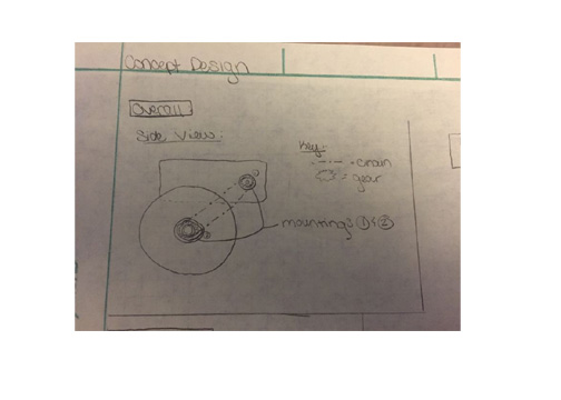
Conceptual Design
Summarize your conceptual design process. Develop at least three concepts.
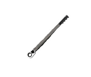
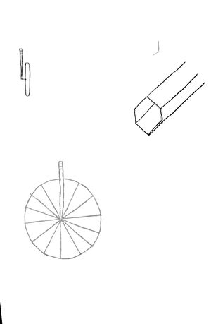
Design Concept 1
- Description:
Hollow bar with a wrench-like attachment on one end, and a handle on the other. The handle will detach from bar to reveal a grabber extension
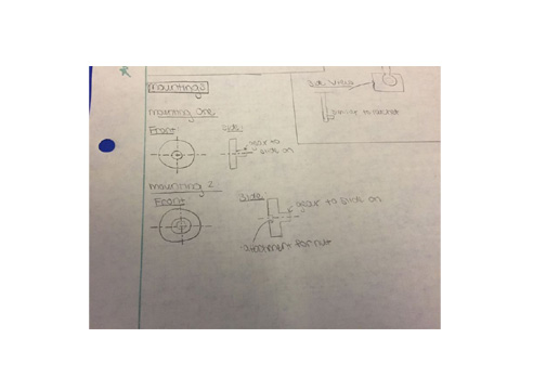
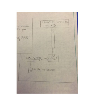
Design Concept 2
- Description:
A gear and chain propelled lever with the lever being attached to a nut using a device similar to a ratchet.
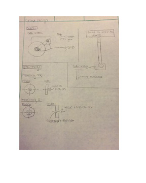
Design Concept 3
- Description:
Customizing a car jack redesign for a wheel chair.
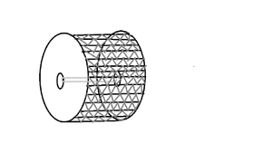
Design Concept 4
- Description:
This is a tire cover for the wheelchair to make going through grass, gravel, etc. involve less effort for the child.
Evaluate concepts/select candidate
We initially chose design concept one as our winning canidate; however, this did not seem to decrease the effort needed to propel the wheelchair forward. After meeting with Dr. Hoover, a physical therapist, and Dr. Canfield, our group decided on a design that adds to the initial lever design. We chose to go with a racecar design, propelled forward with the lever from design concept one with the intention of building upper body strength in a young child.
Detailed Design
Description of selected design
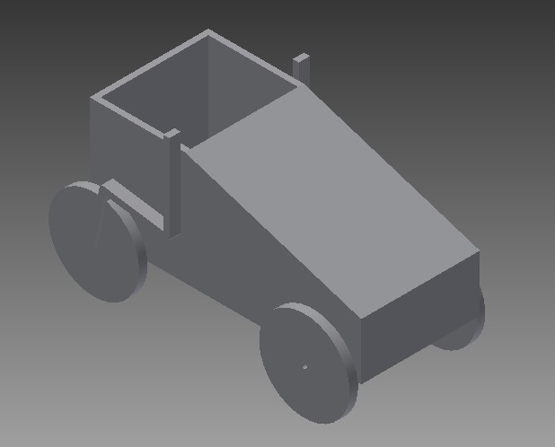
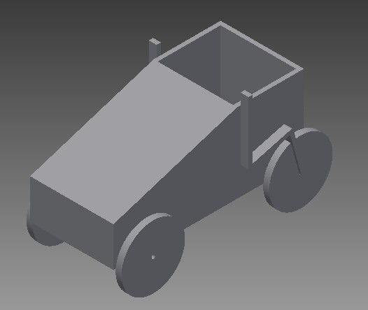
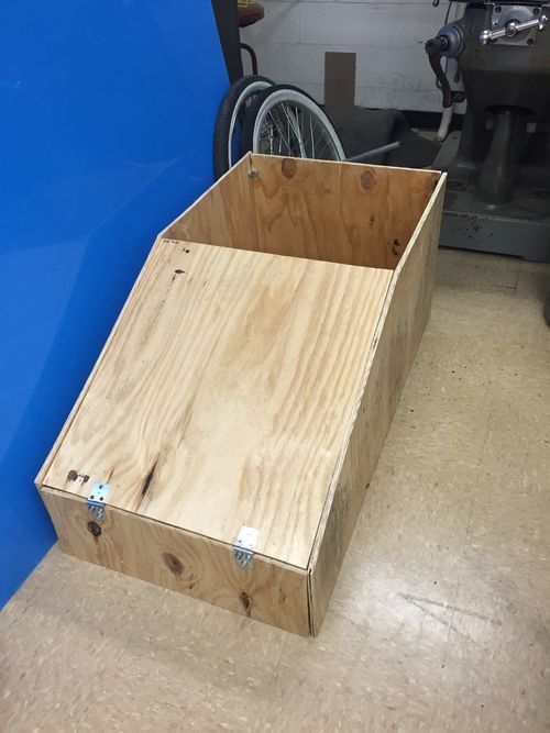
Our group has decided on designing a go kart style toy, that can be propelled forward by levers to build upper body strength in children who lack normal upper body strength.
Detailed description of selected design
Our design can be broken up into 5 parts.
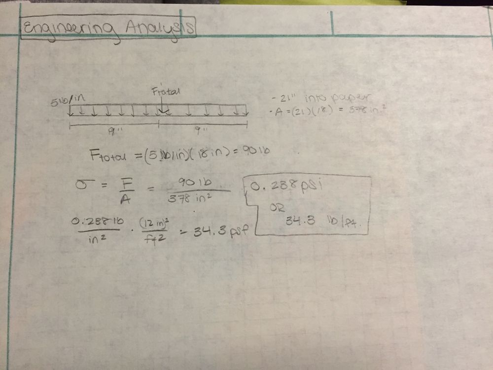
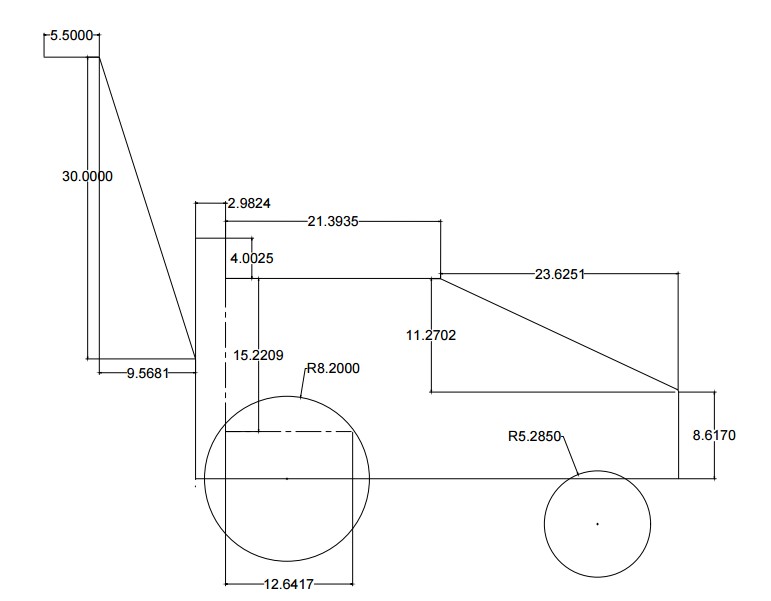
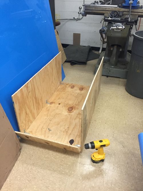
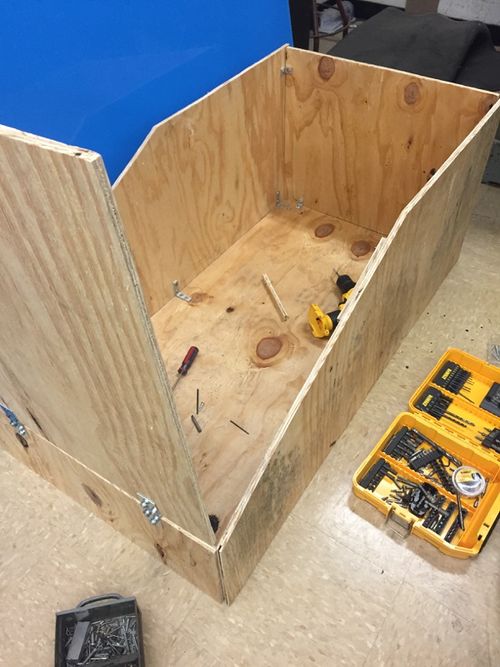
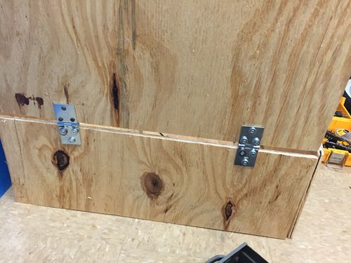
1.) Frame: The frame will be designed the bottom panel can support 90lbs. It will be made of a plywood. The material will be cut to appropriate dimensions connected together by bolts to make a box frame.
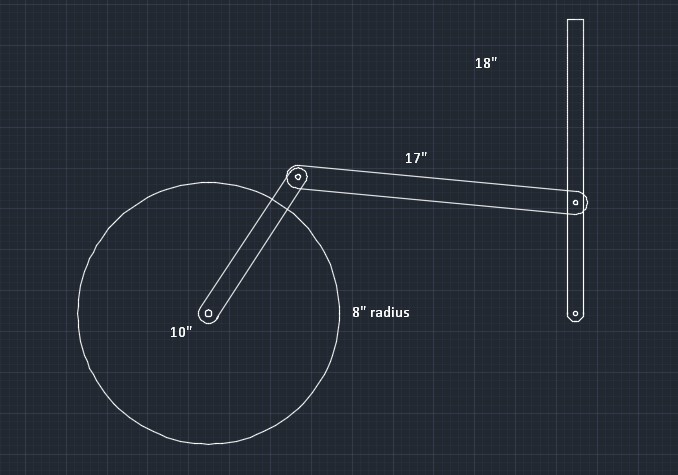
2.) Levers: There will be two levers to be attached to the back two wheels. The levers will be bolted to the gear sprocket to achieve a ratcheting motion. These primary levers will be apart of a larger four-bar mechanism with the input being controlled by the user
3.) Wheels: Our design includes four 26" diameter wheels. Four wheels are being used to increase stability for the child.
4.) Seat (time permitting): The seat will be made of a molding foam so as to conform to the child's body and provide the needed upper body support. There will be seat belts as well that will be able to be tightened. The seat belt will buckle in the middle over the child's chest.
5.) Spoiler (time permitting): To make the go kart more like a go kart, we will be adding a spoiler, like those you see on some cars, made of aluminum. This will be a light addition to the go kart and will make the toy more enjoyable to play with. The adult supervising the child play can also grab onto the spoiler to stop motion of the kart in case of an emergency.
Analysis
Engineering analysis 1
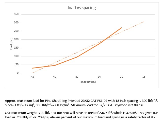
Determining our load allowance and gain assurance that our supplies and design are adequate for its intended job.
Engineering analysis 2
For our second engineering analysis, we decided to do a velocity and torque analysis using a MATLab code listed below. After completing the analysis we were able to find the relationship between the input horizontal force and the output torque in the wheels. With a program written, we were able to change different parameters of our design to give us our desired function.
% Project Velocity and Force Analysis
% Created by : M. Stockdale
% This program will analyze our four-bar velocity and input force
% November 12, 2015
clear all
dtr=pi/180;
% Input values for position analysis:
theta_2_dot = pi/3;
theta_k2 = linspace (80, 150, 71)*dtr;
rk1=12; rk2=9; rua1=8; rua2=20; r2p=9;
theta_k1 = 135*dtr; mg = 53;
% Lengths are in inches and velocities are radians/second
% Begin Loop for analysis:
for j = 1 : length (theta_k2);
   %solve theta_3 and theta_4
   [theta_3, theta_4] = two_uk_angles ( rk1,rk2,rua1,rua2,theta_k1,theta_k2(j), 1 );

   %solve theta_3_dot and theta_4_dot
   A = [ -rua1*sin(theta_3), -rua2*sin(theta_4);
          rua1*cos(theta_3),  rua2*cos(theta_4)];
   b = [ rk2*theta_2_dot*sin(theta_k2(j));
        -rk2*theta_2_dot*cos(theta_k2(j))];
   v = inv(A)*b;
   theta_3_dot = v(1);
   theta_4_dot = v(2);
   Vpx = -rk2*theta_2_dot*sin(theta_k2(j))-r2p*theta_2_dot*sin(theta_k2(j));

   %solve for forces
   %Known: Tw and solving for F_in
   Tw = mg*sin(10)*13;

   F_in = (-Tw*theta_4_dot)/Vpx;

   % Store values
   F_in_store (j) = F_in;
   theta_4_dot_store (j) = theta_4_dot;
   theta_2_dot_store (j) = theta_2_dot;
end
% Plot graphs to show relationships between input and output
figure(1)
plot(theta_k2/dtr, F_in_store)
figure(2)
plot(theta_k2/dtr, theta_4_dot_store)
This program allowed us to obtain two graphs that related a changing angle theta2 to force and angular velocity.
Engineering analysis 3
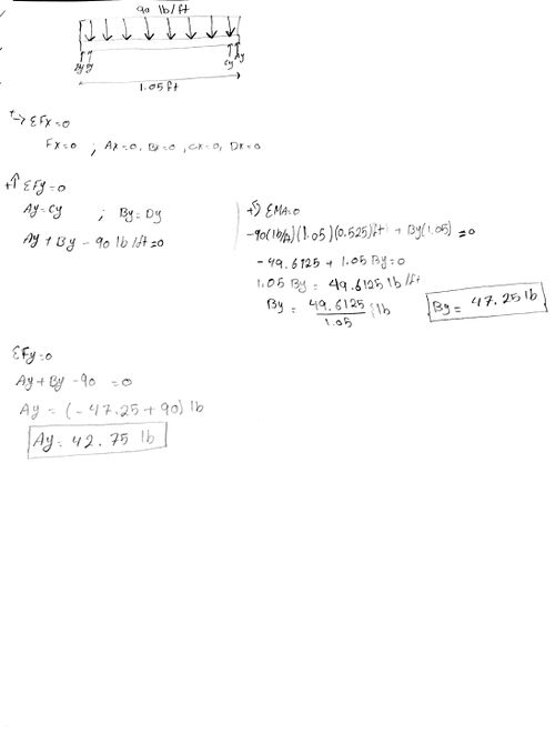
Analyzing the seat to determine the amount of force on our supports that secure the seat to our frame. We did a free body diagram to analyze the forces and the supports necessary for our design to function.
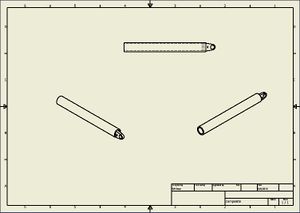
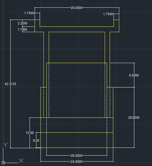
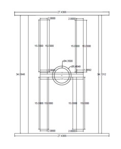
CAD Drawings
Bill of Materials
| Part Name | Specifications | Quantity | Source | Price |
|---|---|---|---|---|
| Bike Wheels (large) | 8" radius | 2 | Walmart | $30.00/wheel |
| Bike Wheels (small) | 4" radius | 2 | Walmart | $30.00/wheel |
| Socket Wrench | Stubbly | 2 | Harbor Freight or Lowes | $9.00/wrench |
| Screws | USP #9 to Coated Torx-Drive Structural Wood Screws | 1 box | Lowes | $9.95 |
| Foam | 2-in x 24-in x 48-in | 2 | Amazon | $90 for |
| Nylon | 10 yards | 1 | Amazon | $7.00 |
| Aluminum Sheets | 1' x 1' | 10 | Amazon | $15.00/square foot |
| Pine Sheathing Plywood 23/32 CAT PS1-09 | 0.703-in x 47.875-in x 95.875-in | 3 | Lowes | $29.97/piece |
| Buckles | N/A | 1 pkg | Amazon | $9.50 |
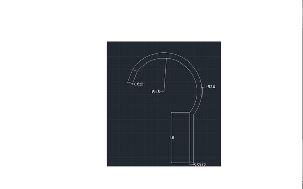
| Handle | see AutoCAD drawing | 1 | 3D printing | still sourcing |
| Lever Bar Hollow | OD: 5/8" ID: 0.555" length: 2' | 2 | McMaster-Carr.com | $13.70/ pipe |
| Aluminum Square Rod (a.) | thickness: 5/16" length: 2' | 1 | McMaster-Carr.com | $4.18 |
| Aluminum Rod Hollow (b.) | OD: 1" ID: 0.902" length: 1' | 1 | McMaster-Carr.com | $9.12 |
| Bearings | 1/2" inner diameter | 2 | Lowes | still sourcing |
Assembly Instructions
- Make frame from plywood according to dimensions. Cut out pieces according to dimensions and drill hole for bearing for lever device.
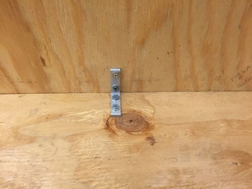
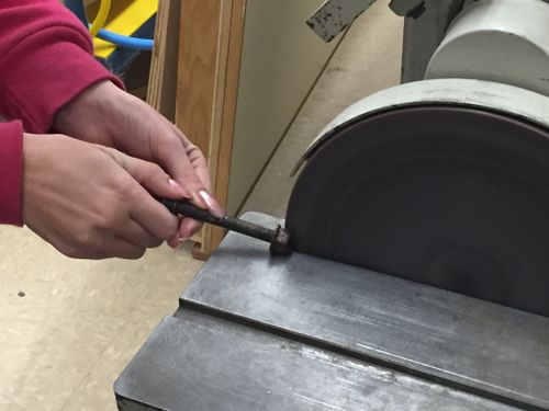
- Assemble the four bar mechanism. Cut and smooth aluminum bars. Bolt together the bars so that they can rotate and attach lever to frame using a bearing.
- Drill two holes in the final lever to fit a bolt. Put bolt head inside a gap in gear tooth on sprocket and bolt to lever. This will create the ratcheting motion desired.
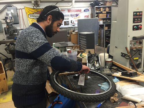
- Attach front wheels using matching size bike wheels with an axle. Drill two holes in the sides of the go-kart of equal height to ensure wheels are level.
- Obtain a rectangular tube and make a clearance for nut that will screw the bike wheel on. Weld these nuts into the openings on both ends of the bar.
- Drill two holes through the tube in order to bolt to the frame.
- Attach back wheels. Both wheels will need the sprockets facing the same way so the wheels will move in the same direction. This requires slightly different assembly instructions for each wheel; however, both will be screwed into the nut on the axle just attached to the kart.
- Right wheel: the sprocket will be facing outward. In order to attach to the rest of the four-bar, you must bend a piece of metal (with the appropriate dimensions to fit design) and bolt firmly to the rest of the four-bar mechanism.
- Left wheel: the sprocket will be facing the kart. Attach four bar mechanism as expected.
Fabrication Process

Testing and implementation
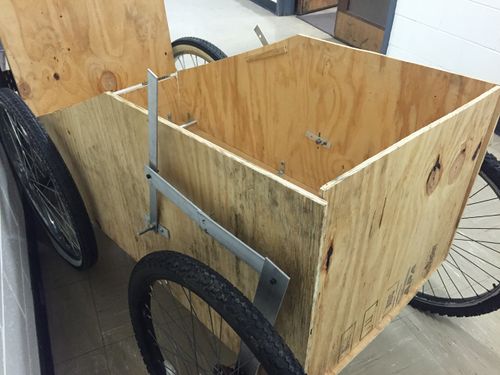
We tested the design with Anne Marie and Dr. Canfield. The kart does move forward, but does so slowly. After inspecting the design, if we had had time to mess with the design, we should enable the lever attached to the bike wheel to have more range of motion. We could possibly do this by changing link lengths in our four bar. However, because this was a proof of concept, we consider this project a success. Project members have thought about possibly coming back next semester to improve upon design in free time.
Photos of Completed design
Instructions for safe use
Make sure you stay seated while using device and that tires are fully inflated. Be on flat ground, and if not make sure someone is supervising to stop go-kart since there are not brakes. Do not use the device unless supervised by an adult that has been fully understood the safe use of this product.
Project Summary, Reflection
This project taught all of us a lot about all the details that go into design. Since we had to scrap most of our parts from the ME shop, we got a lot of experience in the shop. We learned a lot about the amount of work that goes into manufacturing and design and how if details are not clear, the design can be carried out incorrectly. With this project, we were able to apply a lot of class material including force and velocity analysis and MATLab programming. Our go-kart moves forward as expected with some resistance (yet not so much as to be impossible to move) so it would build upper body strength in a child constrained to a wheelchair.