Customized Phone Holder
Abstract
Our client lives with spinal muscular atrophy and scoliosis. She can only turn and lean her head from side to side and move her arms from her elbows down to her hands. We originally came up with three concept designs. After evaluating the designs, we chose a fully mechanical design that has a flexible gooseneck and a phone magnet holder that can rotate at the end. Our final product also included a c-clamp to attach to a wheelchair and a 3-D printed connector piece to attach between the gooseneck and magnet holder. Once the final product was assembled, we met with our client and her family to present the product to them. We attached the product to her wheelchair and showed the family how everything works. We also made sure that the product would be safe and comfortable for our client.
Team members

Team Picture
From left to right:
- Yousef Alenezi
- Darrell Marlow
- Hossein Derakhshandeh
- Nathan Commers
- Daniel Foote
- Daniel Boyer
Acknowledge help of others
- Dr. Stephen Canfield
Problem Statement/overview of the need
Due to her limited mobility and strength, our client is unable to hold her phone in front of her face or up to her ear. Our client would like to use her phone independently. She needs a mechanism that holds the phone in front of her so she can use it.
Design Specifications
1. Must easily mounted and removed from wheelchair when needed
2. Must be easily moved out of the way when not in use.
3. Must be physically easy to use and user-friendly.
4. Must be mistake proof.
5. Must be low-cost.
6. Must be able to hold phones of different sizes.
Background research
There are several comparable devices that can hold phones for people in wheelchairs readily available today. Many of these devices are relatively inexpensive, under $100, but most can only meet a couple of our client's criteria. Most of them hold the phone in front of the user as opposed to having the option for the phone to be brought up the the user's ear. These tend to be rigid devices that cannot be easily moved to the user's preferences.
Conceptual Designs
Design Concept 1
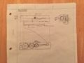
Gear Design
- Fully mechanical; uses a simple gear train to translate rotational motion by the use of a single human input, rolling the input gear either forwards or backwards; clamps to attach to wheelchair arm
- Less-likely to fail than electrical systems; rigid bar is stronger and can hold phone in place more easily, but is harder to get phone exactly where uses would be most comfortable
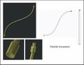
Design Concept 2
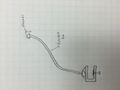
Flexible Neck Design
- Fully mechanical; flexible neck with ball and socket joints; clamps to attach to wheelchair arm
- Flexible neck could fail due to weight, or could become weak through time; unlikely to fail other than by weight; easily adjusted to place phone in comfortable position
Design Concept 3
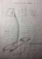
Electrical Design
- Mechanical and electrical; mechanical system with electrically assisted movement; ball and socket joints; clamps to attach to wheelchair arm
- Will need batteries, motors, and most-likely a charger; could fail electrically (wires, buttons, etc.); more user-friendly with the buttons as opposed to moving arm manually (less effort to move)
Evaluate Concepts/Select Candidate
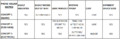
| Categories | Concept 1 | Concept 2 | Concept 3 |
|---|---|---|---|
| Ease of Mounting | 10 | 10 | 10 |
| Moved Out of Way | 2 | 10 | 10 |
| User Friendly | 8 | 8 | 10 |
| Mistake Proof | 10 | 8 | 6 |
| Low Cost | 10 | 10 | 6 |
| Different Device Compatible | 10 | 10 | 10 |
Totals: Concept 1 = 50 / Concept 2 = 56 / Concept 3 = 52
* Concept 2 is the best candidate.
All three concepts are easily attached to the wheel chair with a clamp, and all three concepts can hold devices of different sizes because we are using a magnetic system to hold the devices. Concept 3 is low-cost and easily moved out of the way when not in use, which are both important specifications. The biggest issues with Concept 3 are the effort it takes to move the arm and the flexible neck arm losing strength. The effort required to move the arm should not be so great to not be used, and the flexible neck strength should last for a long time with the right materials.
- Important causes for Concepts 1 and 3 not being chosen:
    * Concept 1 can not be easily moved out of the way
    * Concept 3 is a much higher cost and can fail more easily due to batteries and electrical components
Decision Matrix
Detailed Design
Description of selected design
Rough Final Design
Concept design chosen is based on Concept Design 2. This design includes:
    * C-Clamp like attachment to chair with male threaded end
    * Flexible gooseneck that attaches to top of chair clamp with threaded ends
    * Threaded attachment at top of neck with a ball and socket joint
    * Magnetic phone connection connects to ball and socket joint
    * Magnet in phone/device case
Detailed Description of Selected Design
Analysis
Engineering analysis 1
Mobility Analysis
- Measures the mobility of the customized phone holder once attached to a wheelchair.
- Results:
    * C-Clamp is considered ground once attached (rigidly) to wheelchair arm
    * Flexible gooseneck is considered to have infinite mobility within the reach of the neck
    * Magnetic holder (ball and socket joint) has a mobility of 2 (rotating about both axes)
Engineering analysis 2
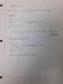
Weight Analysis
- Measures how much weight the flexible gooseneck will need to hold, and whether or not the gooseneck can support the weight.
- Results:
    * Flexible gooseneck should hold up to 2 lbs without drooping
    * Neck can hold cell phone easily
    * Neck might not support a tablet
Engineering analysis 3
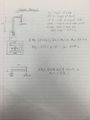
Torque Analysis
- Measures the required torque that the clamp holding the wheelchair needs to be able to support.
- Results:
    * The required torque will be at a maximum when the gooseneck is bent directly to one side or the other
    * This maximum torque required is 1.319 lb-ft
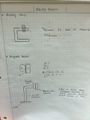
CAD Drawings
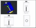
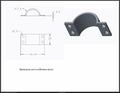
C-Clamp
3-D Printed Clamp Concept Top Half
3-D Printed Clamp Concept Bottom Half
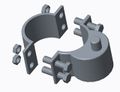
3-D Printed Clamp Concept Assembly
Flexible Gooseneck
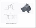
Connector Concept
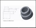
3-D Printed Connector
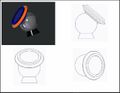
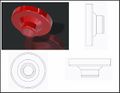
Magnetic Holder
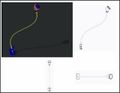
Phone Holder Assembly
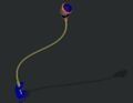
3-D Model
Bill of Materials
| Material | For | Source | Price |
|---|---|---|---|
| C-Clamp | Clamping to wheelchair | OnStage (Amazon.com) | $7.95 |
| 19-inch Gooseneck | Arm | OnStage (Amazon.com) | $7.19 |
| Connector | Connecting gooseneck to magnet holder | 3-D printing | N/A |
| Magnet Holder | Holding phone | Mpow | $16.99 |
- Total Estimated Cost = $32.13 +tax
Assembly Instructions
- Obtain C-Clamp, Gooseneck, 3-D Printed Connector, and Magnet Holder
- Screw C-Clamp and Gooseneck together
- Use epoxy to attach 3-D Printed Connector to Gooseneck
- Use epoxy to attach Magnet Holder to 3-D Printed Connector
- Place magnet in phone case or stick magnet on back of phone
- Attach C-Clamp to wheelchair
Fabrication Process
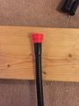
Attaching Gooseneck and Connector
Connection Point / Gorilla Glue Epoxy
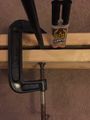
Holding Gooseneck Steady While Epoxy Dries
Holding Gooseneck Steady While Epoxy Dries
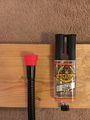
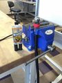
Attaching Connector and Magnet Holder
Gorilla Glue Epoxy
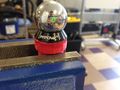
Testing and implementation
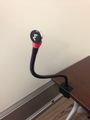
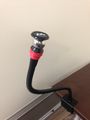
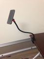
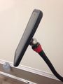
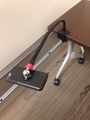
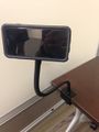
As we got parts in, we tested strength (c-clamp, gooseneck, and magnet strengths). Once assembly was put to together, we tested the attachment of the c-clamp, movement of the gooseneck and magnet holder, and the strength of the magnets (as shown in pictures below of final product). We delivered the product to the family and attched the product to our client's wheelchair. They were very excited to use the mechanism, and not only with phones but tablets, remotes, and other devices.
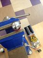
Photos of Completed design
Instructions for safe use
Once product is attached to wheelchair, make sure c-clamp or bolt is not poking or agitating client. Do not violently shake magnet holder with phone or device attached to prevent device falling.
Project Summary, Reflection
As a team, we enjoyed the project. We not only were able to learn more about engineering and get hands-on experience, but we also got to experience helping someone, and that experience is priceless. We all look forward to chances of helping more people in the future, whether the help comes through engineering, community service, or other activities.