Learning toy
Abstract
Our child is eighteen months old and still has not learned to walk. He can walk as long has he has something to hold on to. We need to build a toy that can support him while he walks until he builds the confidence to walk on his own.
Team members
 From left to right: Andrew Davis, William Rogers, Derrick Justes, Jared Miller
Problem Statement/overview of the need
The child that our group is trying to help suffers from NAS, autism, and an injury to his left foot. NAS stands for neonatal abstinence syndrome, which is when a baby is born addicted to a substance and must slowly become sober from that substance. The side effects of NAS cause the child to experience slower growth than healthy babies. Our child is old enough to be walking, however he is still requiring a baby walker to get around the house. The caretaker of the child wants him to no longer require the use of the walker. Another concept we are discussing has to do with the child's diagnosis of Autism. He no longer likes the toys that are attached to the walker he has now, and we are going to attempt to put different attachable toys on the tray of the walker we design. The overall problem that our group faces is that the child requires a newer, taller, more adaptable walker that will be able to keep him happy and moving around the house.
Design Specifications
- Height: 20-25 inches
- Base: 24 inches by 28 inches
- Top: 15 inches by 14 inches
- Support the weight of the child (+30 lbs)
- Open enough for the child to play more freely than standard walkers allow
Background research
1. There are many different designs of walkers that already exist, but the need in this case in not the traditional need of support. It requires a design that is stable enough to support the child but open enough for him to be more free than traditional walkers and allow it to be adjusted in the future so that less invasive support can be removed from the walker as he becomes more independent. Because the ultimate goal of the walker is to assist in helping the child to gain enough confidence to be able to walk without the physiological need of a walker.
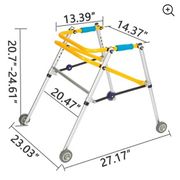
2. The Soft Inc. Baby Walker is one of the more open walker designs we were able to find. A frame based off the frame of the Soft Inc. Baby Walker could be set up to accommodate the top of some other walker by a hinge and a locking mechanism so that the child can be more independent and get into the walker himself.
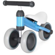
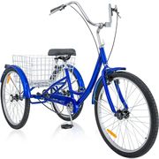
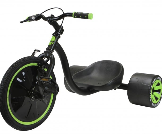
3.) The SKY4786 balance walking tricycle is one of the alternative ideas to a walker. It would allow the child more mobility and be easier to enter and exit at the cost of full body support. modifications would have to be made in order to more fully support the child while still keeping the walking tricycle non intrusive as well as making some modifications to allow the tricycle to be adjustable.
Conceptual Design
Development of a walking device that will allow for ease of use by the toddler, increased mobility, and less parental help entering and exiting the device. The walker should have some component of entertainment, be easy to enter and exit, and provide adequate support in the case of a fall. One of the primary goals of the walker is to encourage the child to walk on his own by giving him confidence in his own ability to support himself. The design concepts all share these qualities but go about achieving them in different ways.
Design Concept 1
Modified Walker (description)
- A frame with similar mobility and design to the Soft Inc. could be utilized as a base for the rest of the design. The top of a more traditional walker could be taken from a walker that we purchase to modify later, or a custom top will be connected to the frame from the back by a hinge and the front by a locking mechanism that is simple enough for the child to be able to operate. This locking mechanism will be based off the locking mechanism found on a Graco Stroller which are in three parts, that can be fixed to the modified top or made as a part of the custom top.
- A removable seat will be a part of the top, that will have a buckle in the front so the child can connect and disconnect it as wanted.
- The most important ideal of this design is that the walker function without the seat with the top or even just with the frame with neither seat nor top, because the ultimate goal is to provide a walker that can be adjusted to assist in the child gaining confidence to walk unaided by a walker.
(materials)
The modified walker could be fabricated with a lightweight aluminum for durability. it could then be covered with a material like a pool noodle so the risk of hurting the child is minimized.The seat would need to be large, supportive, and comfortable.
Design Concept 2
Mobility tricycle (description)
The tricycle would not have any pedals and the child would have to walk around using it as a support system. The tricycle would ideally allow the child to develop balance and confidence while still providing adequate support in case of a fall. The tricycle would have arms on the side to not only support the child but have the option of attaching a "tray" so the child could play with toys while sitting in the seat. This is a secondary goal. The tricycle would also increase the mobility of the child and allow him to use it at his own discretion without the help of a parent. It would need to be made of lightweight material and have an adjustable seat for longer term use. It would need dimensions so a child age 2-3 could use it to walk and be able to hold the weight adequately.
(materials)
The trike could be fabricated with a lightweight aluminum for durability. it could then be covered with a material like a pool noodle so the risk of hurting the child is minimized.The seat would need to be large, supportive, and comfortable.
Design Concept 3
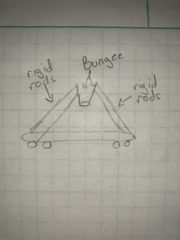
Bungee Cord Seat Walker (description)
For this conceptual walker, the base of the walker would have four wheels around it secured by a metal ring for support. Coming up from the base would be four metal rods that would be a little lower than waist height on the child. There would then be a seat attached to the four metal rods by bungee cords. The purpose of this design would be so that the child could learn to trust himself while squatting and standing. The small support from the bungee would be enough to make him feel secure, while still allowing him to squat all the way to the floor allowing him to pick up desired toys.
(materials)
The walker would be made out of lightweight aluminum for strong support with a softer material around the outside of the rods to prevent injury. The seat would be suspended by bungee cord with a specific spring constant, k, that would be custom to the child’s specific weight.
Evaluate concepts/select candidate
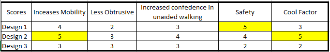
In order to decide the most appropriate design we put together a decision matrix and the canidate with the most points was the second design, which was the adapted tricycle design.
Detailed Design
This section will describe a detailed design process
Description of selected design
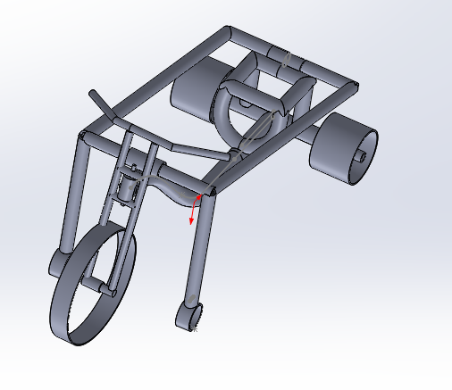
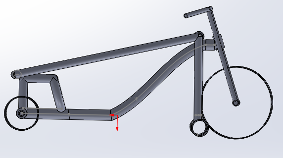
A modified version of a Madd Dog Drift Tricycle with a raised seat and added bars on either side for support.
Detailed description of selected design
Our design will take the existing frame of the Madd dog tricycle and extend the length of its frame to provide more room and freedom of motion. The support bars will connect at the frame directly behind the handle bars and behind the seat. A square structure will be welded to the frame of the tricycle to raise the height of the seat to be high enough for him to sit from a standing position and sit back down easily. The seat will be connected to this square structure.
Analysis
Engineering analysis 1
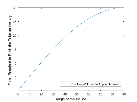
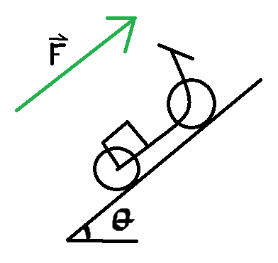
One of our concerns with the Tricycle was that the client may not be able to push it because of how heavy the steel frame is. To check this we used the following Matlab Code to generate a plot of the required force to push the tricycle up a slope versus the angle of the slope. The plot showed that on a slope of 30 degrees, the most weight our client would have to push is about 15 lbs, which is reasonable considering at his age he should not have to be walking up any inclines that are greater than 30 degrees and 15 lbs is not an unreasonable amount of force for the client to push.
%This is a code to define the incline analysis of the tricycle.
%The tricycle's force against the one pushing it is equivilent to the sine
%of the incline's angle multiplyed by the total weight of the tricycle.
W=30;
theta=0:0.00001:90;
Force_the_client_must_push=W*sind(theta);
plot(theta,Force_the_client_must_push);
xlabel('Angle of the Incline');
ylabel('Force Required to Push the Trike up the slope');
legend('The F-vs-M from the Applied Moment', 'The F-vs-M from the weight of the Trike')
Engineering analysis 2
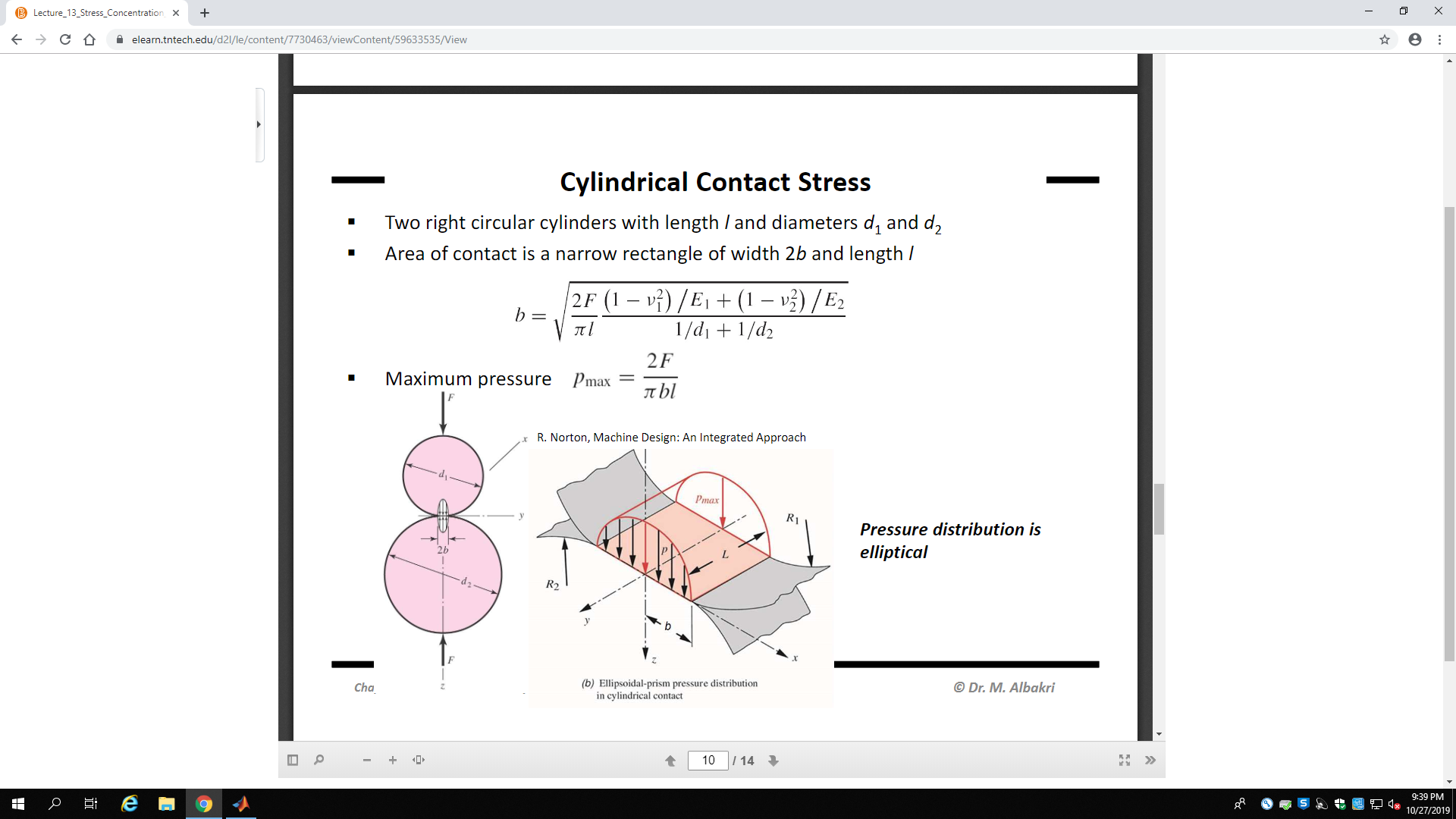
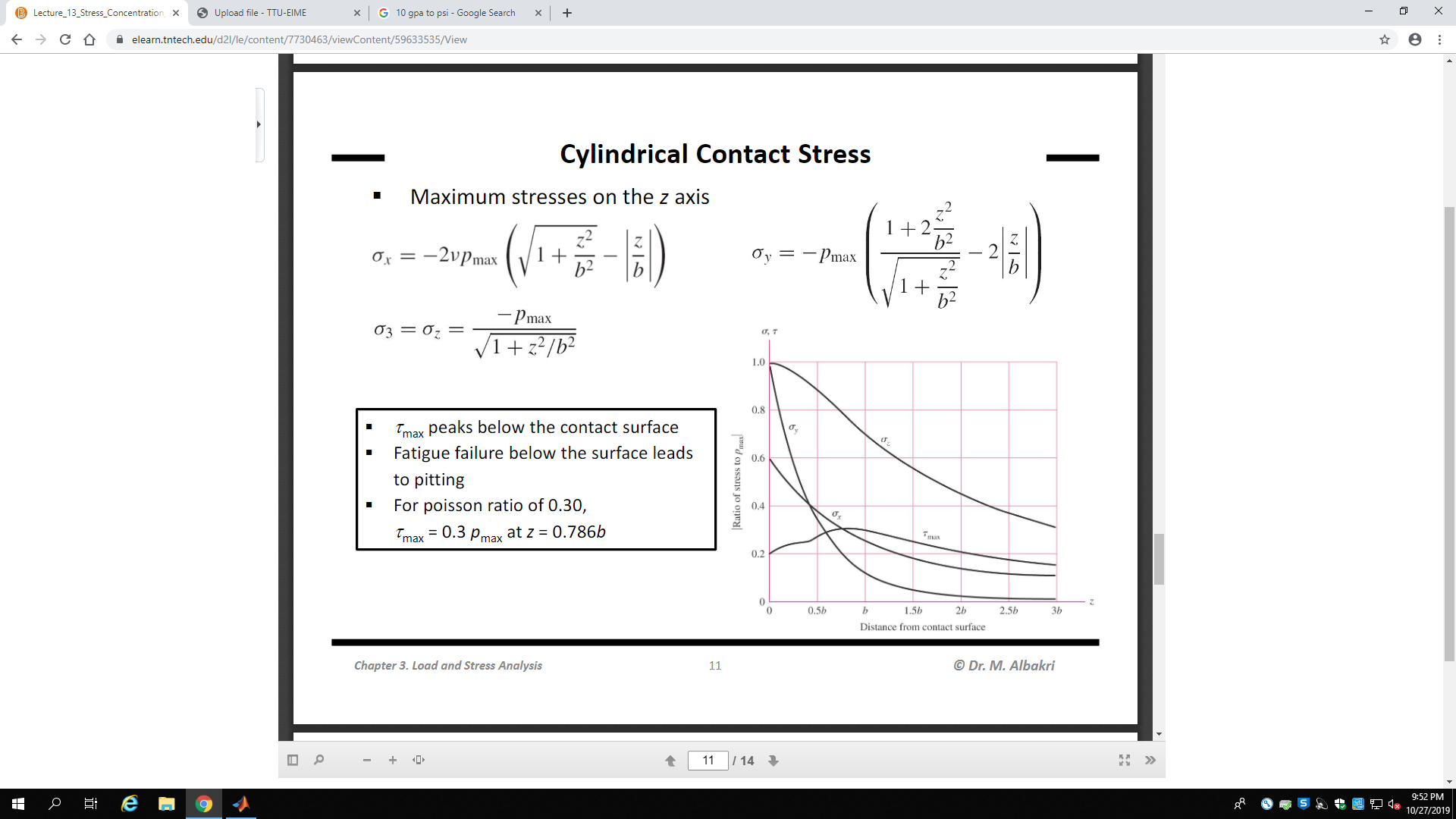
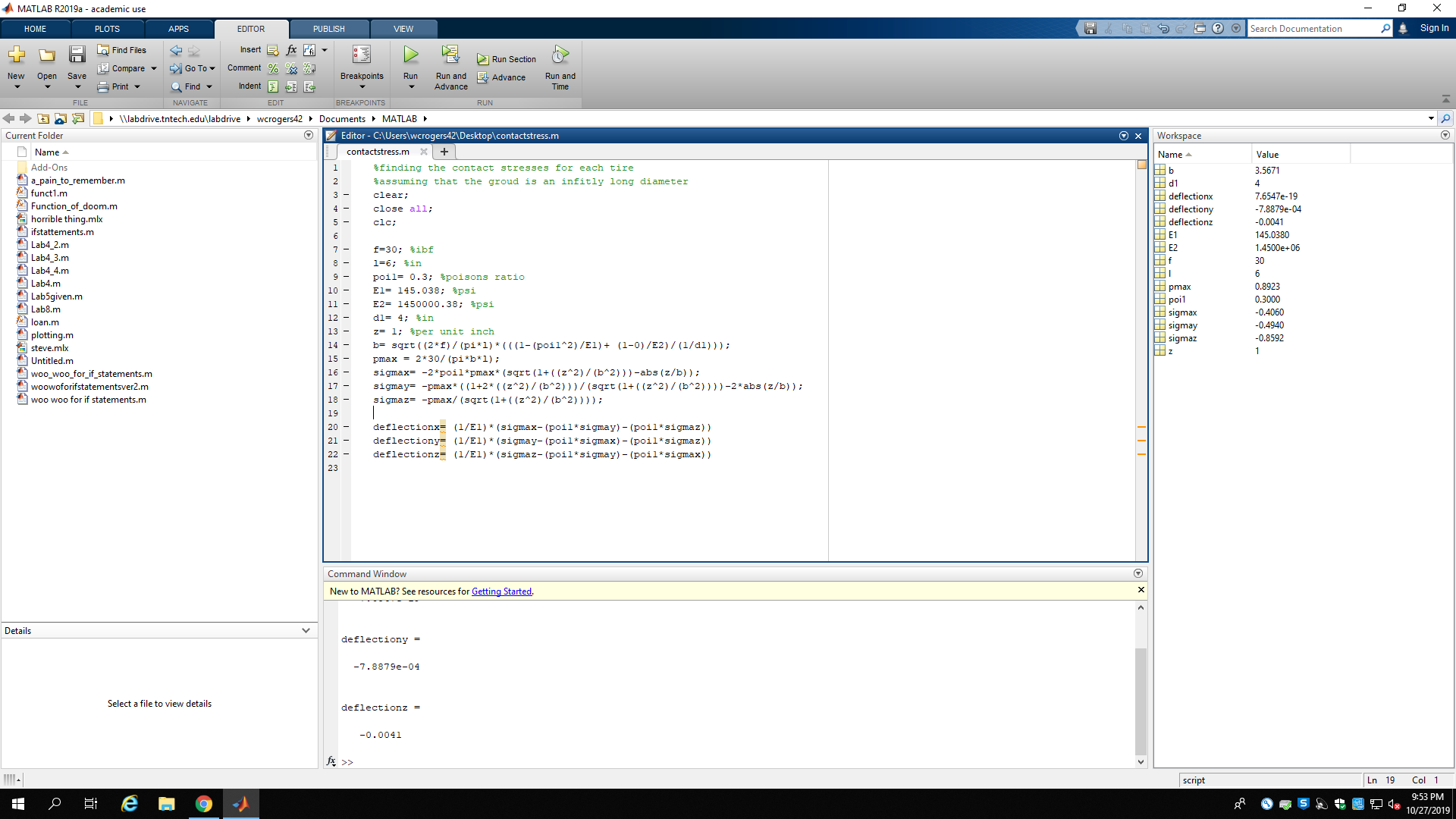
The deflection of the rear tires, those that will be taking the most load, was calculated. These calculations were carried out using approximations of contact stresses on cylinders. we assumed an infinitely long d2, zero deflection on the surface of the ground, and a modulus of elasticity of 10gpa . We also assumed the tires had a poison's ratio of 0.3 and a modulus of elasticity of 1mpa. Lastly we assumed that the total load ,including a rider, would be 60ibs, 30ibs per wheel. The formulas used were from Shigley's Mechanical Engineering Design 10th Edition. The total Strain in the z direction is -0.0041 in/in. Well under any cause for concern due to the added weight of the seat, guide arms, and child.
ref for the Modulus of Tire tread: File:Referenced paper.zip
Edeskar, Tommy. 2004. "Technical and Envirenmental Properties of Tyre Shreds Focusing on Ground
Engineering Applications." Department of Civil and Mining Engineering Division of Soil Mechanics
and Foundation Engineering Lulea University of Technology.
Engineering analysis 3

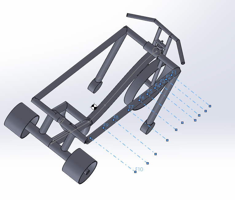
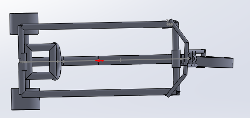
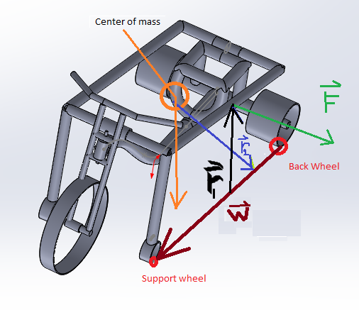
The moment generated by the weight of the tricycle about the w-axis is what resists the tricycle easily toppling over. To ensure that the tricycle is reasonably able to resist toppling over from forces applied on only one side of the
support arms, the moment was calculated from the force applied on the support arms about the w-axis as well. So long as the moment about the w-axis due to the weight of the tricycle is greater than that of the applied force the
tricycle is safe. The graph above was generated using the center of mass calculated by Solidworks based on the assembly file of the tricycle. The vectors were found using end points from the xyz-coordinates of them in Solidworks. Eight different force positions (there are ten postions in the picture but Solidworks crashed after we collected eight) were used to calculate the generated moments, using a range of possible force magnitudes. The average moment generated
about the w-axis from all of the different force positions was then plotted against the applied force of the client on the support arm.
According to our calculations the tricycle will not topple over up to about 75% (16.5 lbs) of our clients current body weight, which is a reasonable amount of resistance to toppling over for our purposes.
The attached zip file contains the Matlab code that was used to calculate the graph and all of the points that defined our vectors.
File:DOM MomentCodeProof.zip

CAD Drawings
Bill of Materials
- 1 Madd Gear Drift Trike as our base trike frame ordered from Amazon at a price of $140.00. Part number B07QQGCNCB
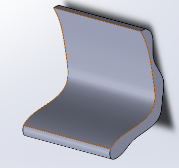
- 1 children's chair bought from Ollie's Bargain Outlet at a price of $13.00. Part number 883562001299
- 2 5 ft lengths of 1" diameter ASTM A53 schedule 40 steel pipe ordered from McMaster at a price of $50 each. Part number 7750K233
- 3 5 ft lengths of 0.75" diameter ASTM A53 schedule 40 steel pipe ordered from McMaster at a price of $37 each. Part number 7750K232
- 1 3 ft length of 0.75" diameter ASTM A53 schedule 40 steel pipe ordered from McMaster at a price of $23. Part number 7750K192
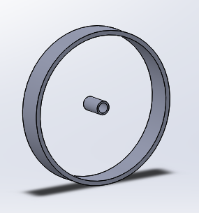
- 2 Socket Caster Wheels with a diameter of 2.5" ordered from McMaster at a price of $48 each. Part number 2248T31
Total Cost for Project = $487
Assembly Instructions (with pictures)
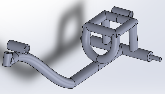
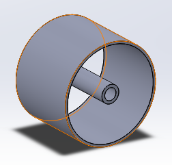
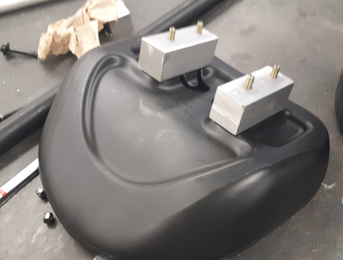
First, to raise the seat, two 2x2-inch and 4.25-in long sections of rectangular aluminum bar were used to make the seat a little taller to help it be easier for the client to sit comfortably from a standing position. The length of the frame was also extending by cutting the frame where it was most horizontal and inserting a 6-inch length 2-inch diameter steel pipe, inside between the two separate pieces of the frame then welded into place.
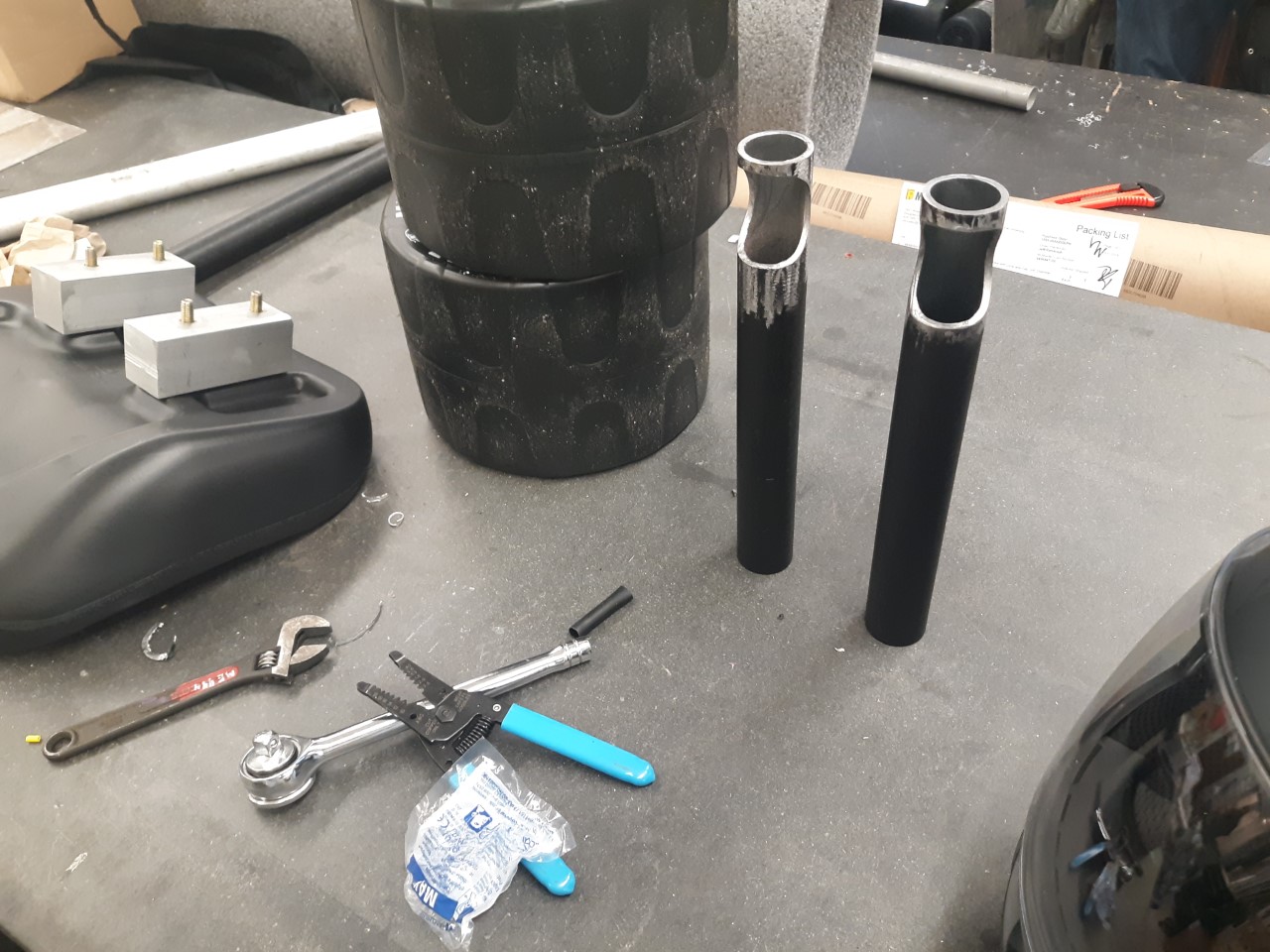
Next, the one-inch diameter steel pipe is cut into two 7-inch-long pieces. These lengths of pipe then each have a 2-inch hole cut through the edge of the pipe with a hole saw. These holes are cut half an inch from the end of the pipe. These two steel pipes are then welded onto the back axle an inch from the back wheels. Another 6-inch length of 1-inch diameter pipe was cut and had the same kind of 2-inch diameter hole cut through the middle of it. This second length of the steel pipe was welded on the front section of the trike’s frame.
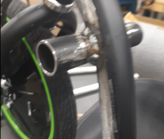
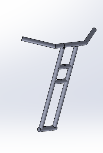
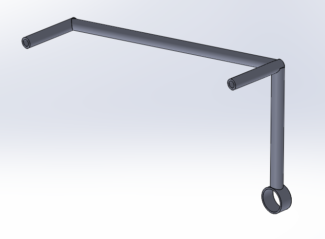
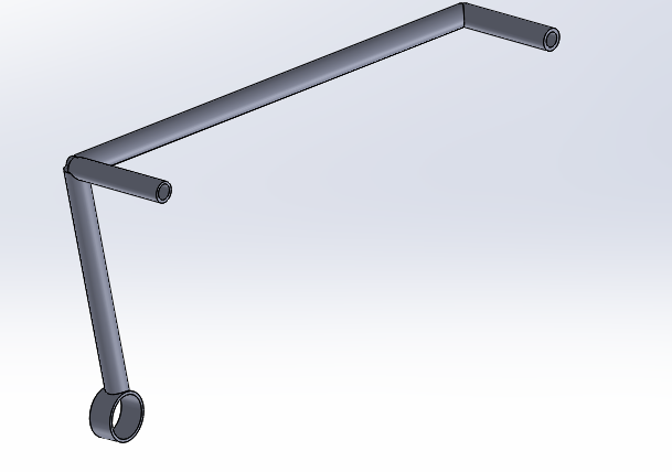
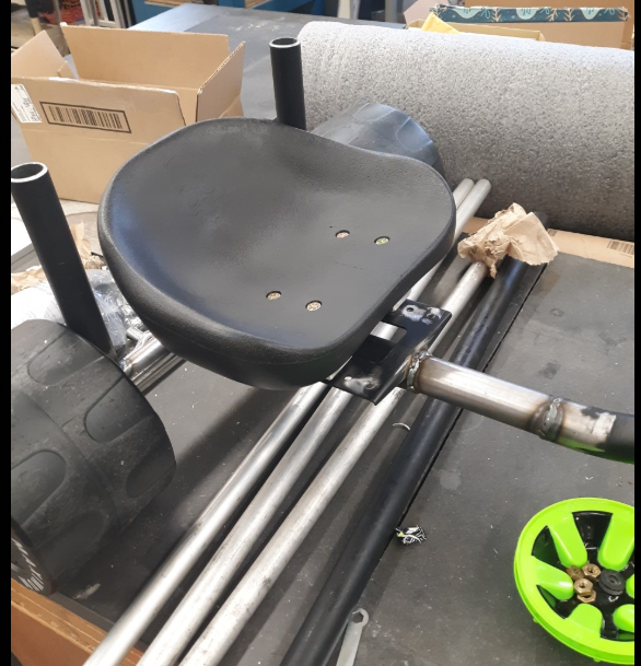
The last part of the process and the most important was to make the arm supports that help to support the client in walking. To do this we used aluminum 1-inch diameter pipes: two sets of 27.5-inches, 6.5-inches, and 5-inches in length of each were cut. The 6.5-inch and 5-inch pieces had 1.125-in holes cut into them using a hole saw to aid in our positioning of the welds for the arm supports. These were aluminum pipes so the cuts had to be ground down so they were flush against the 27.5-inch pieces before welding. After the cuts had been ground flush, the arm bars were welded together, and then the outside and inside edges of all the pipes in the assembly were thoroughly sanded to prevent any sharp edges from being present. After all of the surfaces were smooth and the welds were cool enough to touch, the Trike was fully assembled in order to see how it all fit together.

The final step was to cut another set of aluminum pipe about 22.25-inch long out of 1-inch diameter aluminum pipe that would be welded to the arm supports and have the casters on the ends of them in order to prevent the trike being tipped over easily. These pipes were cut and then had the 1.125-inch diameter hole cut through the end of them on the side that would be welded to the arm supports. Then they were welded to the arms after being sanded flush to the arms so that the aluminum welds hold.
The casters were attached by drilling a hole through the ends of the arm support pipe and putting a bolt through the hole, which was then fastened by a nut. Finally, the trike was primed, and painted. We went with a splatter paint, and followed the original theme of the Madd Dog trike and kept the black and green colors.
Testing and implementation
The trike was tested by members of the team walking around in it to see how well it could be steered from within the side support arms and it worked well. We also tested for the trike tipping over, and it was satisfactorily difficult to tip over.
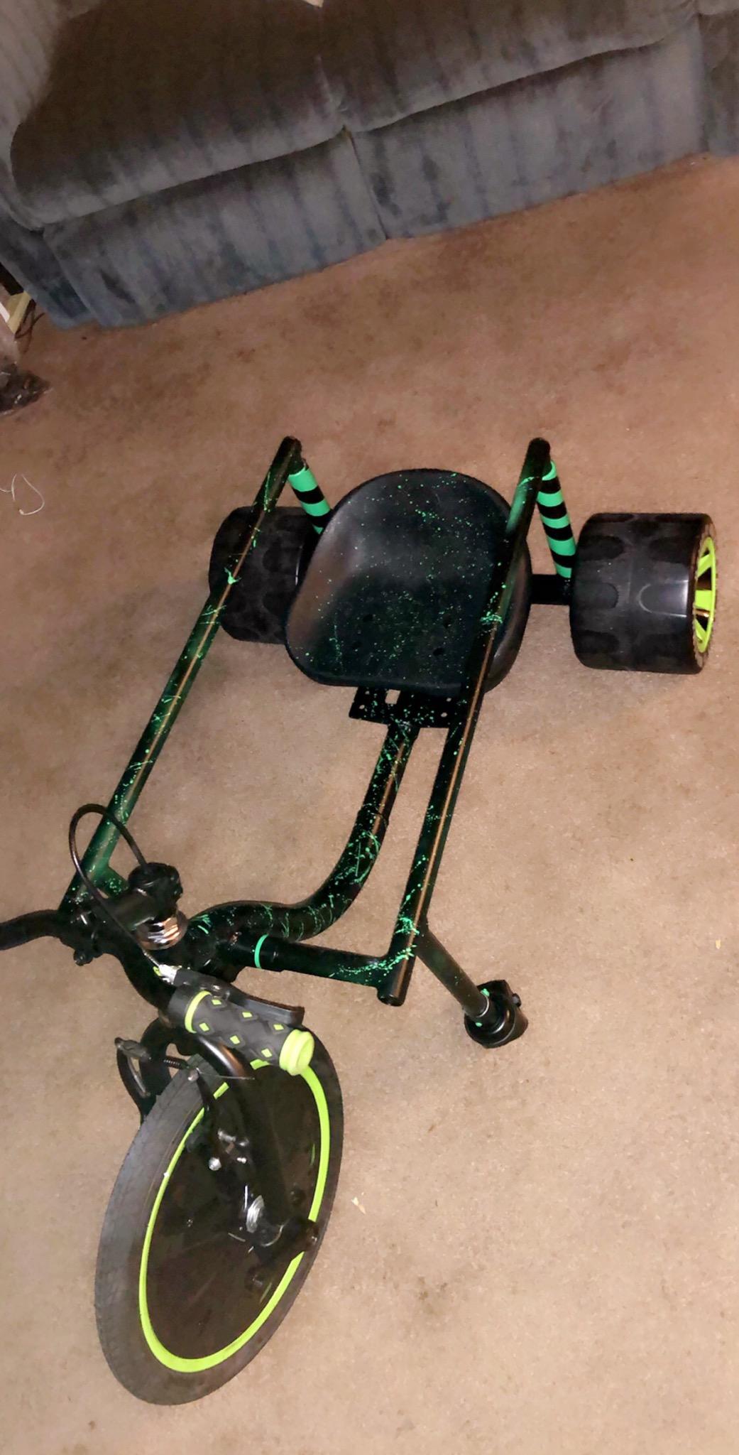
Photos of Completed design
Instructions for safe use
It is important that the seats position be adjusted to the comfort of the client before it is used as a walking aid. The seat is attached to the frame by four bolts that are tighten by nuts. The seat can be adjusted closer to the handlebars or further depending on the client's preference.
To begin using the mobility tricycle the client stands inbetween the handle support arms and the seat of the trike and begins walking while holding on to the handle bars to steer the trikes front tire as the client walks.
The only danger when operating the mobility tricycle it is important that the area around the tricycle is clear of small objects that could cause the front wheel to shift suddenly and become unstable.
If the client wants to begin using the mobility tricycle like a regular tricycle this can be accomplished by removing the handle support arms by pulling them out from their rear posts located on the rear of the frame then reinstall the pedals of the trike by screwing them back into their sockets which are located on either side of the front wheel.
Project Summary, Reflection
We were presented with a client that was unable to walk but lacked the confidence to walk unaided by a Walker. Our solution was a tricycle that had room to walk while it was straddled by the client. This trike would also have to be approachable so that other children would want to interact with the client more. Finally the trike had to be capable of being converted back into a regular tricycle when the client is confident walking unaided.
This was accomplished by modifying a child size drift tricycle. The frame was extended for more walking room, the seat was raised to be more comfortable to sit into from a standing position, and support arms were added on either side to help the client feel more comfortable walking in the trike.
This project was a challenge both in deciding how to solve the problem and how best to implement our solution. We are confident that we made the right decision with the mobility tricycle, that it will support our client's needs, that it will still be useful as a regular tricycle after our client has gained the confidence to walk unaided.