Mobility Scooter
Abstract
This project involves the design, testing, and implementation of an assistive crawling device for therapeutic use in children with developmental issues. The equipment will be used to stimulate coordination between a child's cognitive ability and motor skills.
Team members

- Kody Strange
- Lake Lowe
- Mary Taylor
- Shozo Shimbo
- Kyle Crass
- Yousef Alenezi
Acknowledgements
- Dr.Steven Canfield
Problem Statement/overview of the need
Crawling helps to develop balance, strengthen muscle tone, and develop hand-eye coordination. This is necessary for future reading, writing, and physical activities. Bilateral integration is improved through crawling as both hands, legs, eyes, and ears are required to work in synchronisation, increasing left and right brain co-ordination. The crawling movement is repetitive and this stimulates brain activity to develop cognitive processes such as concentration, memory, comprehension and attention.
The device is intended to aid children with developmental issues that inhibit the natural ability to crawl. Future issues in the child's development could be less severe or eliminated by addressing the inability to crawl early in their life.
Design Specifications
- Support child 150lb and 40in tall
- Have weight < 50lb
- maintain noise level < 80dB
- Durable enough to endure prolonged abuse
Background research

Crawler
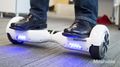
Self-balancing scooter
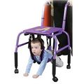
Suspension crawler
There are currently no prone ridden scooters on the market that can be powered without use of a handlebar. By using the frame of a crawler being powered by a readily available self-balancing scooter, a prone scooter could be achieved without using a handlebar.
Conceptual Design
Design Concept 1
Design Concept 2
Design Concept 3
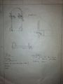
Concept 3
Detailed Design
This section will describe a detailed design process
Description of selected design
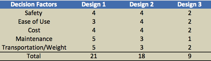
As a team, we have determined that Concept 1 will be the best solution to our customer's needs. We evaluated each design quantitatively based on safety, ease of use, cost, maintenance, and portability/weight. In nearly every aspect, we believe this design for a (prone) mobility scooter will go above and beyond the capabilities of design 2 and design 3. It will offer left of right steering, forward movement, as well as reverse, which is a feature our customer would like to see. In addition, it is lightweight; therefore, transporting this scooter in a classroom setting will be easier and safer for the client.
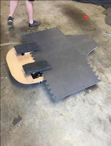
Detailed description of selected design
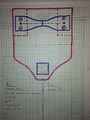
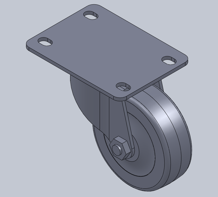
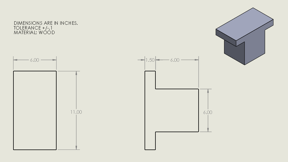
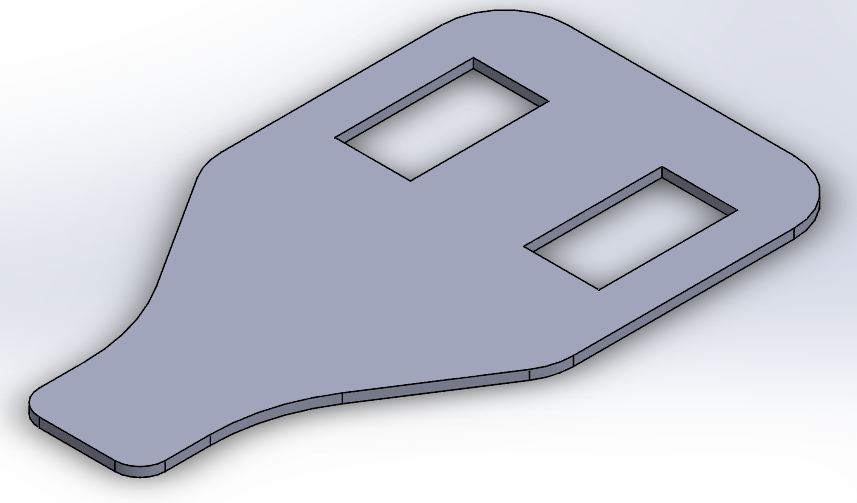
This mobility scooter will consist of a hover board, a 30in x 40in wood support for the child to lay on, a caster wheel for rear support, and two 4.5in x 12in 3D printed arm rest plates. Due to the fact that the hover board relies only on 2 pressure sensors per side, it will be rigidly attached to the wood support in the center with 4 bolts. Two arm rest plates will then connect to the pressure sensors with enough clearance to set them above the surface of the wood support. The child will rest their forearms on the arm rests, which will then allow them to transfer pressure forward, backward, left, and right. As a result, the pressure sensors will give an input to the hover board's circuit, causing it to move accordingly. In the rear, 4 bolts will attach a freely rotating caster wheel to the wood support, offering support and movement in any direction.
Analysis
In this section, we will be evaluating four aspects of our design with engineering analysis techniques. For our first analysis, we are determining the minimum power required by the hover board to move the scooter under load. Secondly, we determine the stresses experienced by the wood support under load, and compare that to the yield stress of wood. Third, the maximum deflection the wood support will experience is evaluated. Lastly, the support reactions on the rear caster wheel are determined.
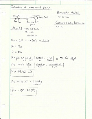
Engineering analysis 1
In this analysis, we set the design parameter for our scooter's speed to be 5 mph. We also set the maximum loaded weight to be 150 lbs. Then we evaluated how much power the hover board must produce to be able to overcome a force of rolling resistance, which combines friction, gear inefficiencies and other factors that would cause resistance to movement. We determine that the power output needed must be greater than 100 Watts, or .133 HP(Electric).
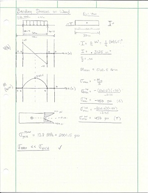
Engineering analysis 2
For analysis 2, we are determining the maximum bending stress that the wood will experience in order to compare that value to the yield stress of our wood type. For this, we put a distributed load of 5 lb/in over a 30 inch portion of the board. This represents the weight of the materials, as well as a child lying on the board. We then determine shear and moment diagrams to yield a maximum moment. Then, this moment can be used to evaluate bending stress. We determine that the maximum bending stress is more than 4 times less than the yield stress of plywood.
Engineering analysis 3
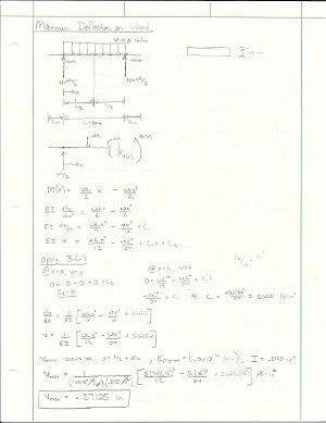
Analysis 3 is used to determine how much the wood support will deflect. Similarly to analysis 2, we but a distributed load on the wood to simulate a child lying across it. Due to symmetry, we know the maximum deflection will occur directly in the center of the board. As a result, we know that the wood will deflect a maximum of .37125 inches downward.
Engineering analysis 4
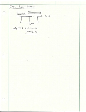
Analysis 4 is a simple evaluation of the support reactions on the rear caster wheel. As a result of static equilibrium and symmetry, the result is half of the weight applied to the board. In evaluating for a maximum possible weight on the board to be 150 lbs, the support reactions will be 75 lbs.
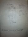
CAD Drawings
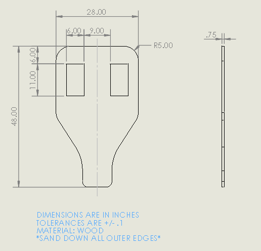
Insert drawings of all parts and the assembly
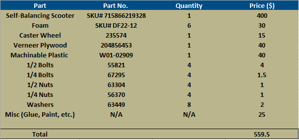
Bill of Materials
Assembly Instructions
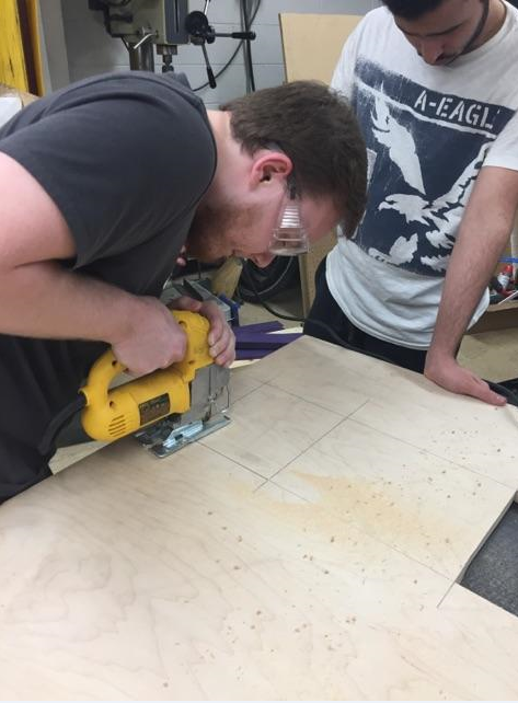
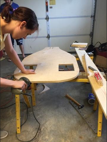
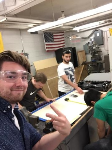
Fabrication Process
Insert pictures of fabrication process
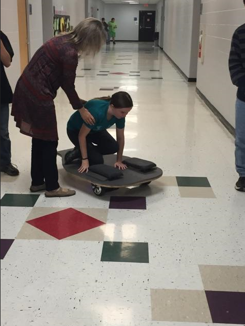
Testing and implementation
Describe testing, delivery, how used/received by the family
Photos of Completed design
Insert pictures of the final product
Instructions for safe use
Provide a clear summary of safe use for the family. Do not use the device unless supervised by an adult that has been fully understood the safe use of this product.