Modified Prone Crawler F14
Contents |
Abstract
Design and fabricate a device that will allow a child to develop the proper motor skills and muscle mass needed to learn how to crawl.
Team members
- Andrew Schussler
- Wes Demirjian
- William Gaetjens
- Jon VanDoran
- Jesse Schmitz

Problem Statement
This device will be used for an individual child for a unique amount of time and will then be cycled to another child. The goal is to allow a child to be able to lay in it while having the ability to maintain a proper crawling position. This support needs to allow the child the ability to move around and develop the control and strength required to crawl by itself.
Design Specifications
1. Must be able to roll on indoor surfaces
2. Must allow the child to stay in a crawling position
3. Must have clearance for a feeding tube on the left side
4. Must have head support to take strain off neck
5. Must cost less than $500.00 (unless it can double as a walker)
6. Must accommodate the standard body size of a 6 month – 2 year old child
7. Must support up to 50 pounds
8. Must be compact enough to fit through doorways
9. Must be light enough so that an infant can move it
10. Prefers to be able to break down into smaller parts
11. Prefers to be able to transform into a walker
Conceptual Design
Summarize your conceptual design process. Develop at least three concepts.
Design Concept 1
Pros:
- •Compact design
- •Simple to construct
- •Low center of gravity
Cons:
- •Head support/body length is not adjustable
- •Can't be transformed into a walker
- •Frame is less rigid due to excessive use of sliding joints
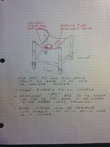
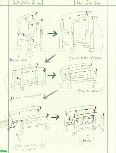
Design Concept 2
Pros:
- •Fully adjustable to transform into a walker
- •Every part can be detached
- •Telescoping sections allow for the walker to be as compact as the crawler
Cons:
- •Head rest could be dangerous
- •Cradle is not sufficiently supported
- •Baby's back will be arched inward causing strain on the neck/vertebrae
- •Additional parts needed to transform crawler into walker
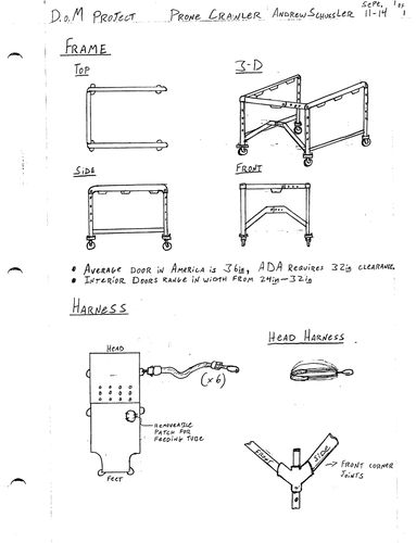
Design Concept 3
Pros:
- •Very durable due to joint connections
- •Cradle is fully adjustable and supported in seven locations
- •Ability to transform into a walker
- •A-shaped bar in the front will not hinder the child when crawling while keeping design fully adjustable
Cons:
- •Potential hazards due to head harness
- •Cradle could be uncomfortable due to buttons
- •A-shaped bar in the front may be in the child's line of sight
Evaluate concepts/select candidate
- Safety: Quality measured from possible hazards resulting from design failures or accidents
- Comfort: Quality measured from ease of grief
- Performance: Quality measured from compatibility with child's training while learning to crawl
- Ease of Use: Quality measured from convenience of assembly, disassembly, and adjustment
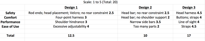
- Based on the totals, we are building our prototype to model Design 3.
Detailed Design
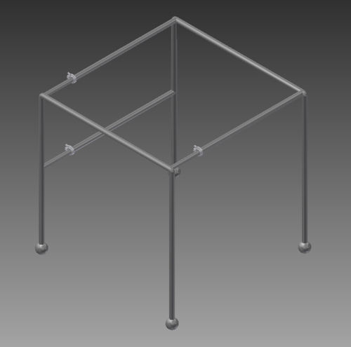
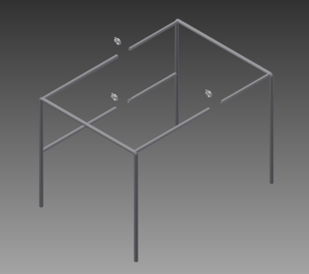
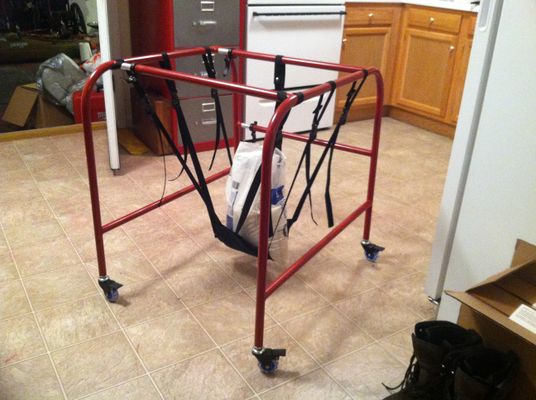
We have based our final design primarily off our third design. After further discussion with our therapist, we have decided to focus just on the crawler aspect of the design and forget about transformation into a walker. However, we have still maintained some sense of adjustability through the front and rear telescoping cross bars.
Our selected design consists of a bent and welded steel frame atop four casters. Our frame has two sides, each with three protruding stems that telescope into one another. Our casters have the ability to lock the rotation of the wheels, making the device safer.
Cam-Action Clamps are being implemented to secure the length of the telescoping rods that extend from the main frame. These are the same devices used on adult bicycle seats, so we know for sure that they are strong enough to handle the compressive loads created by a child's weight. Further, all families using our device should be familiar with how these mechanisms work resulting in almost no learning curves.
Analysis
We performed three different engineering analyses on our machine. We evaluated the frame's weight, the amount of stress each Cam-Action Clamp has to withstand, and the worst-case-scenario total stress on the frame due to the child's weight.
Engineering analysis 1: How much does the steel frame weigh?
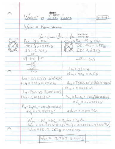
At first, we thought steel might be too heavy to use. However, from this analysis, we discovered that might not be the case. Because the pipes are hollow and the walls are thin, our crawler will only weigh around 14 pounds.
But since this device is going to be used for an infant, we decided to go with aluminum (assuming we would be able to bend it successfully). Aluminum would be a lot lighter (by about half) and would still provide ample support for small children.
Engineering analysis 2: How much force will each Cam-Action Clamp have to withstand?
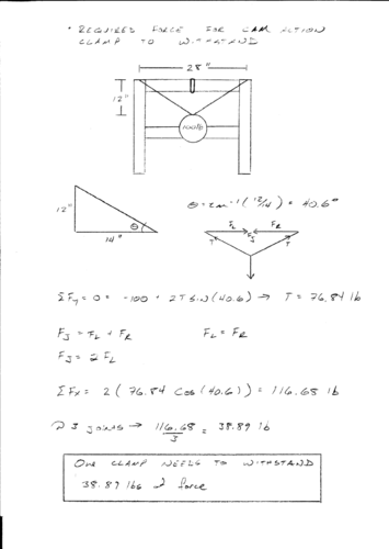
As stated above, these clamps are commonly used in the bicycle industry to support bike seats. That means they are often under compressive stresses from full-grown adults. This analysis reinforces that these clamps will be sufficient in keeping the telescoping rods from slipping.
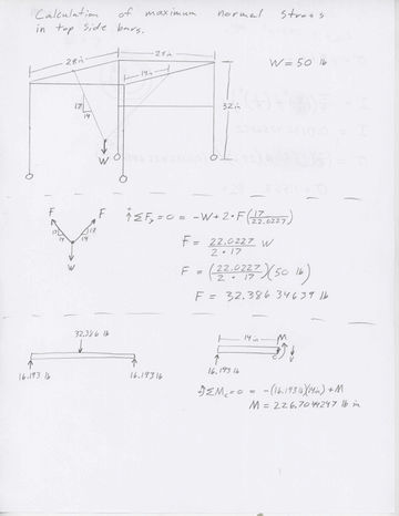
Engineering analysis 3: What is the total stress developed on the frame?
 |
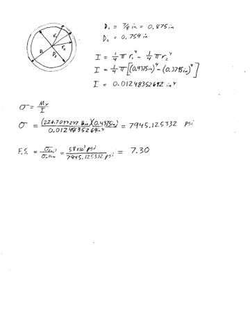 |
On this analysis, we assumed the heaviest child possible was hanging only from the two side bars. This worst-case-scenario examination showed us that our design has a large factor of safety. This is mostly due to the frame being made out of steel.
CAD Drawings
Most of our CAD drawings were created from Audodesk Inventor. The dimensions are labeled on the drawings.
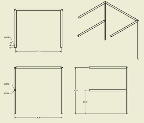
One side of the frame (female).
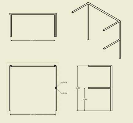
The other side of the frame (male).
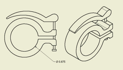
The clamps holding the telescoping bars in place.
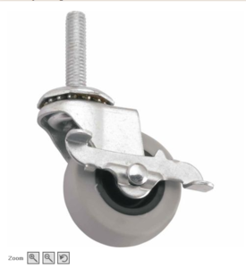
The style of locking casters we're using.
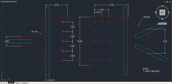
The sling we're going to make.
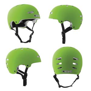
The type of helmet we'll use for the head harness (one size fits all).
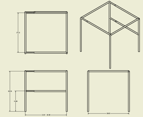
Our full assembly (without the casters, head harness, and sling).
An exploded view of our assembly (without the casters, head harness, and sling).
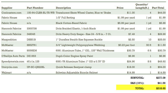
Bill of Materials
Our completed parts list is presented below.
Fabrication Process
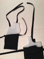
Sling
• A big thanks to Mrs. Demirjian for doing all our sewing!!
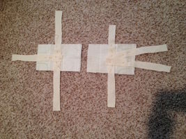
We started by constructing a half-scale model out of scrap fabric and extra batting to see if we could find any flaws with our design.
1st Layer
Add Batting
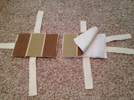
2nd Layer
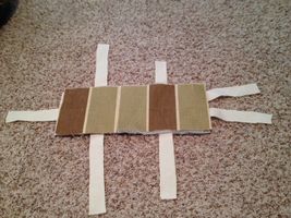
"Snap" Together
Since our model seemed to work, we constructed the prototype.
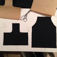
Cutting fabric from a 1:1 scale pattern
Cutting batting from 1:1 scale pattern
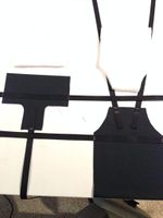
Inserting the batting into the fabric
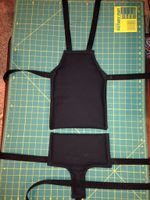
Sewing it all together
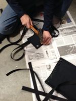
Hammering in the snaps
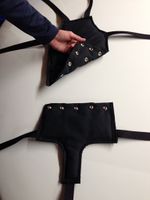
Final product (separated)
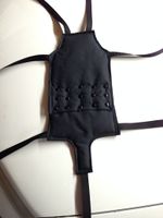
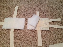
Final product (together)
Testing the sling
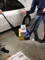
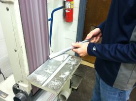
Bending the Sides
For each side of our crawler, we used one 8-foot piece of aluminum pipe and bent it twice at 90˚ angles using a pipe bender.
Because we didn't want our tubes to pinch at the corners or collapse on themselves, we first filled each tube with sand.
Filling with sand
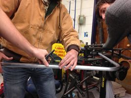
Making sure our bends were parallel
Bending the pipes
How we actually bent the pipes
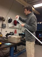
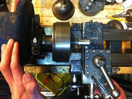
Cutting Pipes
To make the crossbars, we started with two sticks of 6 foot aluminum piping (one stick for the larger telescoping rods and one for the smaller) and cut them down to an appropriate size.
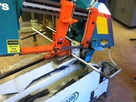
Cutting the pipes with the saw
Deburring the insides of the newly cut ends
Sanding down the outsides of the newly cut ends
Preparing the ends of tubes to be welded by milling
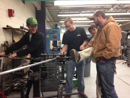
Welding
• A big thanks to Mr. Perry for doing all our welding!!
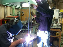
Welding the support legs
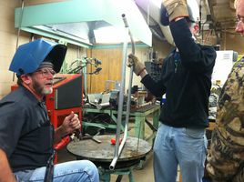
Master aluminum welders
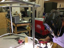
Welding the telescoping rods
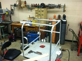
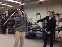
The (almost) final product
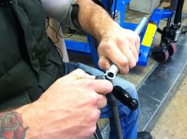
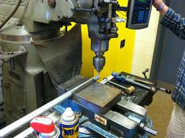
Threaded Inserts
In order to get our casters to stay in our frame, we made some custom inserts that would fit into the bottom of our frame. These are threaded so the casters can screw into place.
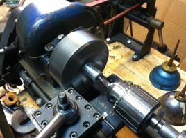
Boring the inserts
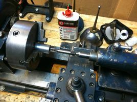
Tapping the inserts
Turning the inserts to fit the ID of our frame
Painting
We care about the crawler doing the job. They care about the crawler doing the job and looking good. We aim to please.
Priming the frame
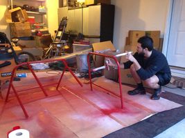
Painting the frame
Photos of Completed Design
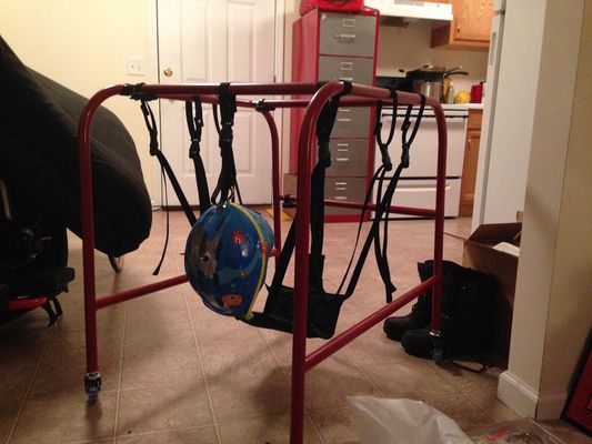
Finished product
Finished product strength test
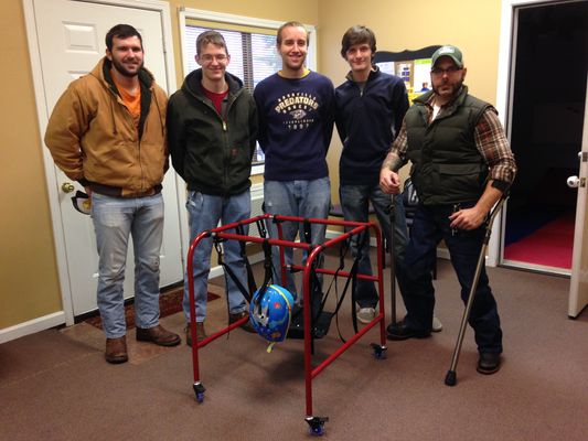
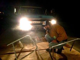
Delivering the crawler
Assembly Instructions
Assembly is easy! Just follow these simple instructions:
THE FRAME
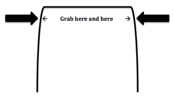
- To adjust the frame's width, unfasten the clamps by lifting up on all three clamp arms, slide the frame to the appropriate width, then push the clamp arms back into the secure "locked" position (the clamps work like those on a bicycle seat).
- Note: For least resistance when adjusting the frame, push/pull by grabbing both vertical bars just below the curved portion at the top (see picture below).
- To lock the casters, press the piece of black plastic extending from the wheel toward the floor HARD. You won't break it. They are difficult to press because in the locked position, they are very secure. To unlock, pull up on the same piece of plastic.
THE HARNESS
- To detach the harness, squeeze the sides of a buckle and pull apart until it releases (they work like buckles on a life jacket). Repeat for all remaining buckles.
- Note: The entire harness is machine-washable! After removing it from the frame, you can toss the whole thing in both the washer and dryer.
- To adjust the harness's length, unsnap all five buttons on the harness by pulling the two individual pieces of the harness in opposite directions, perpendicular to the direction of the snaps. Line up the snaps to the appropriate length and push all five snaps back together. An audible "SNAP" will be heard to confirm they are secure.
- Note: By unclipping the front two straps on the harness (while keeping the other five attached to the frame), it is easier to place child in the harness before reattaching the front two straps.
Instructions for safe use
- This device has been designed to support up to 50 pounds. Loading the frame or harness with a weight greater than this amount could result in serious injury to the user and destruction of the device.
- When the wheels are in the locked position, do not forcefully attempt to roll the frame. The wheels will withstand light pressures when locked, but too much could result in damaging the locks and rendering them useless.
- Do not sit on, lean on, stand on, lie on, or place things on the device (except for its intended use of supporting a small child with the harness).
- Cam action clamps are a choking hazard. Do not leave children unattended with the device.
- Do not use device on sloped or slippery surfaces.
- Always use ALL the straps (head harness is optional).
- Wheels could possibly roll over child's fingers. To avoid this hazard, adjust the frame's width to an appropriate size before use.
- Do not use the device unless supervised by an adult that fully understands the safe use of this product.