Night Rider S14
Contents |
Abstract
The project required the team to create a system with which a visually-impaired child would be able to ride a tricycle without worrying about running into objects that came into the path of travel. The team was tasked with creating a proof of concept system that could be easily implemented onto the tricycle system at a later date.
Team members
- Eli Ramsey
- JL Mitra
Problem Statement/overview of the need
A young child with vision impairments has need of a tricycle system that can be ridden without fear of running into objects that may not be seen.
Design Specifications
For this particular problem, the following specifications apply:
- System needs to notify user of either clearest path or closest object
- Notifications should come to the user in adequate enough time for the user to react to information
- System needs to be implemented on a tricycle meant for a small child
- System should be completely self-contained to keep wires or other components from interfering with safe operation
Conceptual Design
Our conceptual design will make use of ultrasonic sensors mounted on the tricycle to detect obstacles in the user's path, and give feedback to the user via vibrating motors in the handlebars.
Detailed Design
Our design will make use of 3 ultrasonic sensors mounted between the tricycle handlebars to detect obstacles. Ultrasonic sensors were chosen due to sunlight causing interference issues with IR rangers. We chose the MaxBotix MB1200 sensors for their analog voltage output and a built-in ability to chain multiple sensors together to avoid cross-talk.
These sensors are positioned such that a sensor is placed in the middle of two other sensors, facing directly ahead of the user at a 0 degree heading. The other two sensors are placed on either side of the middle sensor, angled slightly left and right of the middle sensor at 30 degree offsets.
Using a resultant vector strategy, the readings from these three sensors will be used to determine feedback (position and intensity) on the vibrating motors under the left and right handlebars. Since each sensor has a known angle from the forward heading, the direction of each sensor's vector corresponds to its placement (offset angle). The analog voltage reading from each sensor determines the magnitude of that sensor's vector. Using trigonometric functions to decompose each sensor vector into X and Y component vectors, all three sensor's X components and Y components are summed to determine the X and Y components of the resultant vector. This resultant vector will then point in the direction of travel for the user in order to avoid obstacles detected by the sensors.
In our implementation, the positive X-axis corresponds to the 0 degree forward heading, and the Y-axis corresponds to the left and right directions. Our feedback model makes use of taking the magnitude of the resultant vector to correspond to the duty cycle of the PWM signal sent to the motors (controlling vibration intensity), and the sign of the Y component of the resultant vector determines which motor to vibrate (positive Y vibrates the left motor, negative Y vibrates the right motor).
Bill of Materials
| Product | Manufacturer | Manufacturer Part Number | Supplier | Supplier Part Number | URL | Unit Price (USD) | Quantity | Total Part Price (USD) |
|---|---|---|---|---|---|---|---|---|
| MaxBotix MB1200 XL-MaxSonar-EZ0 | MaxBotix | MB1200 | MaxBotix | MB1200 | Ultrasonic Sensor | 44.95 | 3 | 134.85 |
| Motor Driver | Texas Instruments | L293NE | DigiKey | 296-9519-5-ND | Motor Driver | 3.75 | 5 | 18.75 |
| DIP Sockets for Motor Driver | CNC Tech | 243-16-1-03 | DigiKey | 1175-1477-ND | Dip Sockets | 0.225 | 10 | 2.25 |
| Molex Female Connector Housing | Molex Connector Corporation | 22-01-2077 | DigiKey | WM2016-ND | Female Connector Housing | 0.381 | 20 | 7.62 |
| Connector Crimps | Molex, Inc. | 0008500159 | DigiKey | WM9847CT-ND | Connector Crimps | 0.124 | 50 | 6.19 |
| Flat Rainbow Ribbon Cable | Assmann WSW Components | AWG28-08/F-1/300-R | DigiKey | AE08B-50-ND | Ribbon Cable | 24.23 | 1 | 24.23 |
| Total | 193.89 |
Sensor Housing Complications
Upon completion of the code for this project, the team mounted the three sensors in the housing unit created by the previous design team. When testing this setup, we found that the sensors gave improper readings when resting on a stand. The team believes that this is due to some resonance in the mount caused by the ultrasonic sensors. Our recommendations for this are to create a new sensor housing unit using a material that will be less affected by resonance from the sensors.
Because the team was unable to proceed with the project as a whole, we decided to test our code using one sensor and prove that what we had completed would work when ported over to the next stage of development.
Code Listing
Source code for ultrasonic sensors running on a Dragon12-Plus2 development board.
/***********************************************
* ECE/ME 4370 US Sensor Demo                   *
* J.L. Mitra (jlmitra42@students.tntech.edu)   *
* Eli Ramsey (egramsey21@students.tntech.edu)  *
* 06 May 2014                                  *
************************************************/

#include <stdio.h>
#include "MCU.h"

void main(void)
{
  int data, data_l, data_h;
  char *message;

  PLL_init();
  ad1_enable();
  lcd_init();
  SCI0_init(9600);

  message = "SW5: start";
  set_lcd_addr(0x00);
  type_lcd(message);
  while (!SW5_down()); // Wait for SW5 press
  message = "Sending data... ";
  set_lcd_addr(0x00);
  type_lcd(message);


  while (1)
  {
    data = ad1conv(0);
    set_lcd_addr(0x40);
    write_int_lcd(data);
    data_l = data & 0x00FF;
    data_h = data >> 8;
    outchar0((char)data_l);
    outchar0((char)data_h);
  }
}
Source code for real-time plotting of ultrasonic sensor readings using MATLAB.
function dragon2matlab_cont();
keepLooping = true; % loop until false
lHandle = line(nan, nan); % Generate a blank line, return the line handle
loopCounter = 1; % keep track of iterations
timeOffset = 0.01024*6; % not perfect, but close
s = serial('COM7','BaudRate', 9600, 'DataBits', 8);
fopen(s);
C = onCleanup(@()fclose(s)); % close the connection when quit (CTRL+C)

while keepLooping
    X = get(lHandle, 'XData');
    Y = get(lHandle, 'YData');

    data = fread(s, 1, 'int16') * (5/1024);
    time = (loopCounter - 1) * timeOffset;
    X = [X time];
    Y = [Y data];

    set(lHandle, 'XData', X, 'YData', Y);
    loopCounter=loopCounter+1;
    title('Ultrasonic Sensor Voltage','FontSize',14);
    xlabel('Time (s)','FontSize',12);
    ylabel('Sensor Voltage (V)','FontSize',12);
    drawnow;
end
Ultrasonic Sensor Testing
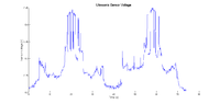
Upon completion of the code listed in the previous section, the team tested the code and a single sensor using two methods. First, the team went into the Mechatronics lab at Tennessee Technological University and went to one of the workbenches. We then ran the program and passed the sensor back and forth around a U-shaped area between the work benches. The results of this test can be seen in the first image located to the right.
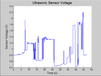
For further testing, the team went into Brown Hall room 208 and, after raising the sensor system above the desk and chair space, the program was run and the team performed a sweep around the room. The results were then graphed and can be seen in the second image located to the right.
Summary and Conclusions
The design team was tasked with improving the design of a tricycle meant for a child with vision impairment. To accomplish this, the team chose to redesign the code and mount new sensors. However, while trying to implement the changes, the team ran into difficulties that prevented them from fully completing the project as specified. Because of this, the team performed an experiment that would show that the code that had been created would be sufficient to accomplish the task at a later date.
Design teams in the future will need to create a new sensor housing unit that will not react to the resonance of the sensors. In addition to this, a future team will need to implement the output from the board to the motors for feedback. The current design team believes that this process will be relatively simple to implement given the code that has been completed. When these changes are implemented, the most important aspect will be ensuring the wiring is clean and easy to maintain when the final product is constructed.