Novel riding toy
Contents |
Abstract
Walking comes natural to most kids without disabilities and is often overlooked by most since it comes natural after the young learning curve. For those kids with disabilities, the ability to not be able to walk is a huge hindrance in everything from their social life to physical well being. This is where problems meet solutions, the F18-15 EIME project is developing a therapeutic walking system that is not only ergonomic, but a logistical solution to the needs of the young development stages. This system needs to be reliable in support the weight, but versatile enough to allow growth, but not limited to these parameters.
Team members
Problem Statement/overview of the need
The child we are working with has upper body strength but needs help developing the use of her legs. To assist with this learning process her parents and therapist asked that we design and manufacture custom parallel physical therapy bars with a locking tray on top and adjustable lengths and width so the bars will adjust as the child grows.
Design Specifications
Our original design parameters included several limitations that had to be designed around. The most crucial design parameter happened to be the height and width limitations. We had to work around the the variation that the child will under go during the growing process while meeting her need to increase stability for the evolution of her walking phenomenon. Other limitations included such as designing a walking system that would have enough mobility for a mother by herself, as well as supporting the weight of a developing child.
Background research
As a team we collectively researched the logistical needs for a support structure as well as the mobility that we could achieve. Not only did we research the machine specifications, but we looked into what location of the therapeutic walking rails, in reference to the waist of the child, what would be most beneficial to the development of her walking. Other research also included, other methods than parallel walking rails such as a concentric walking system.
Conceptual Design
Therapeutic Walking System Design Concepts
Design Concept 1
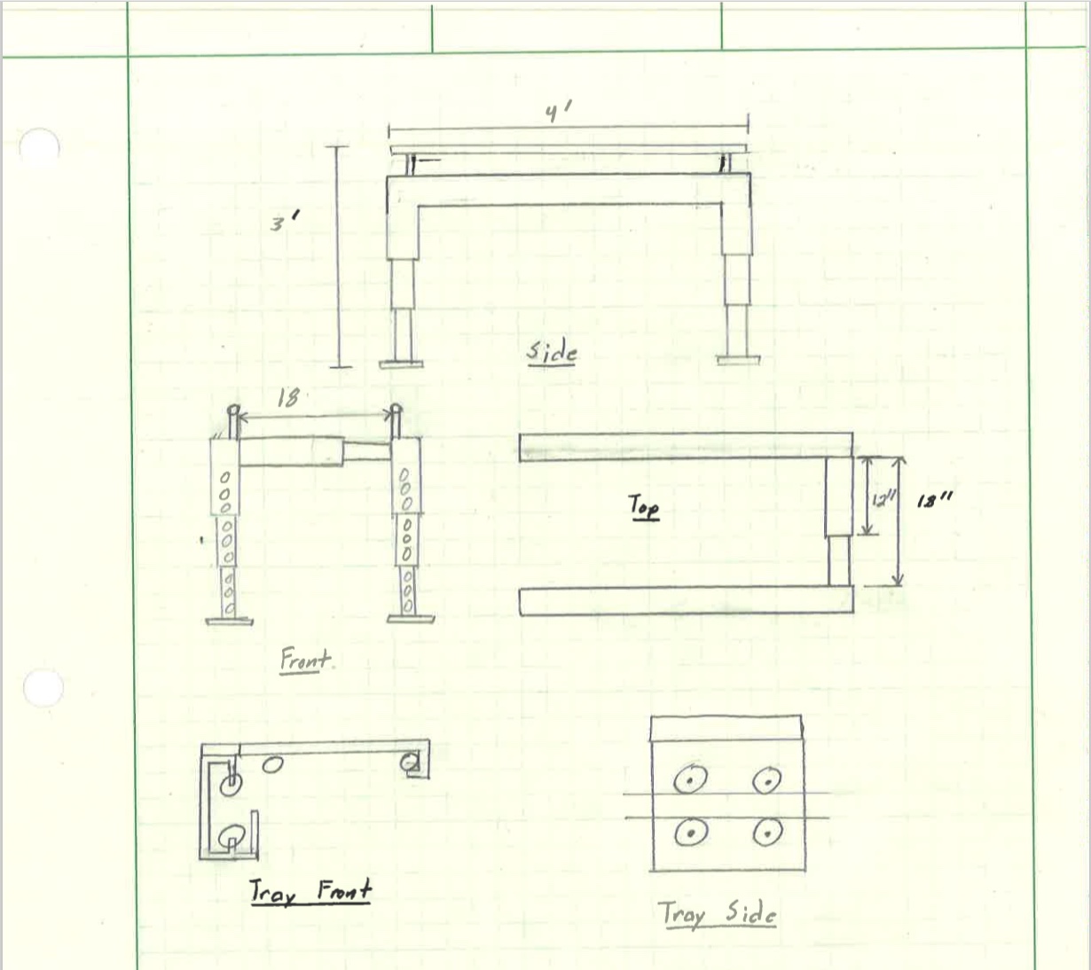
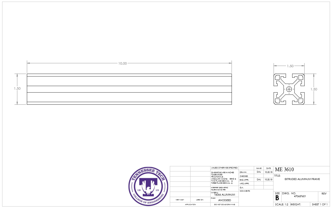
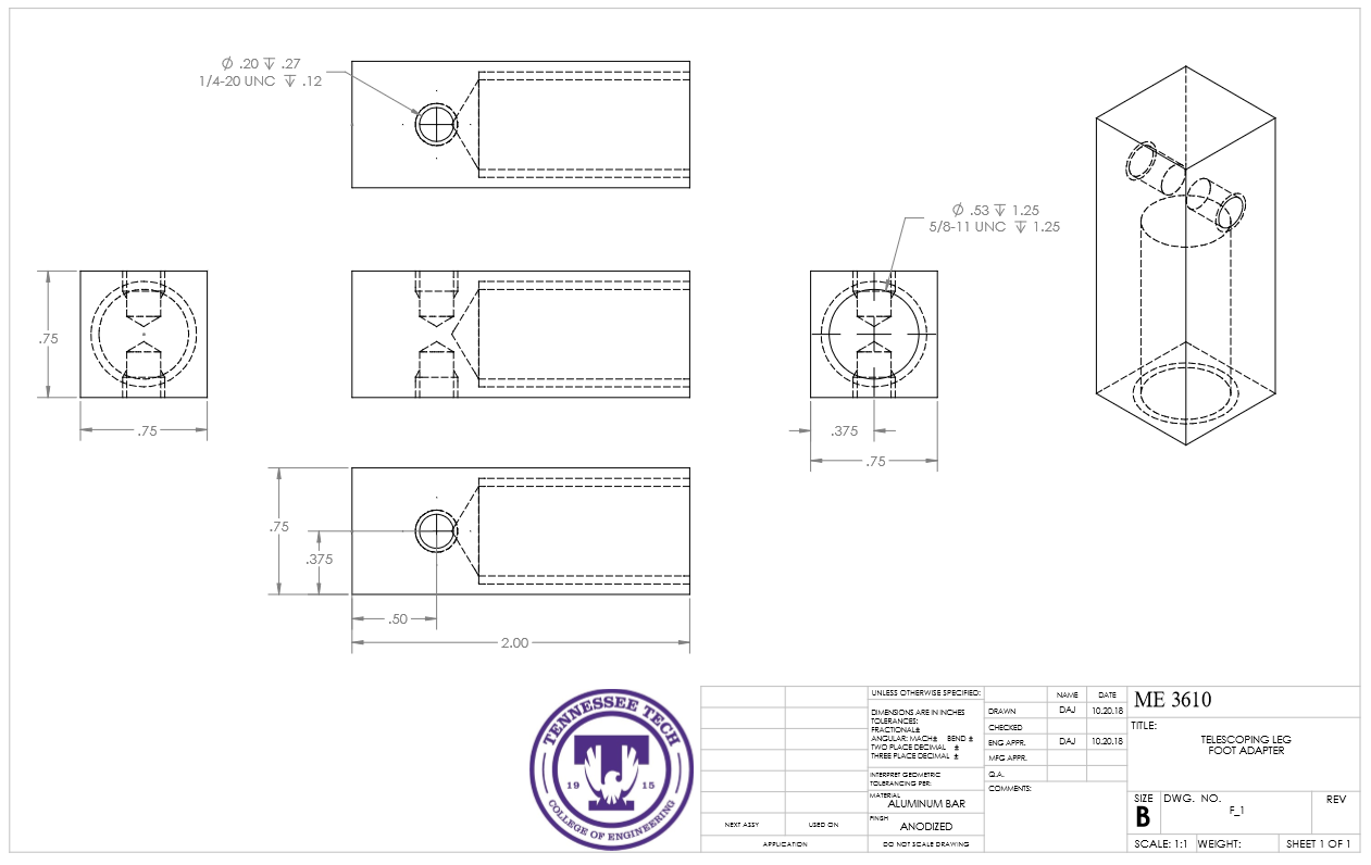
This design was created with variation in mind and mobility as a priority. With telescoping legs, the system can decrease to a size of 12" from the floor to the bottom of the rail to allow the child to start using it as soon as possible. With extruded aluminum as the main frame support system, the system is estimated to be under 50 pounds, while costing less than $250 in manufacturing cost. (Estimated)
Designed By: David A. Johnson
Design Concept 2
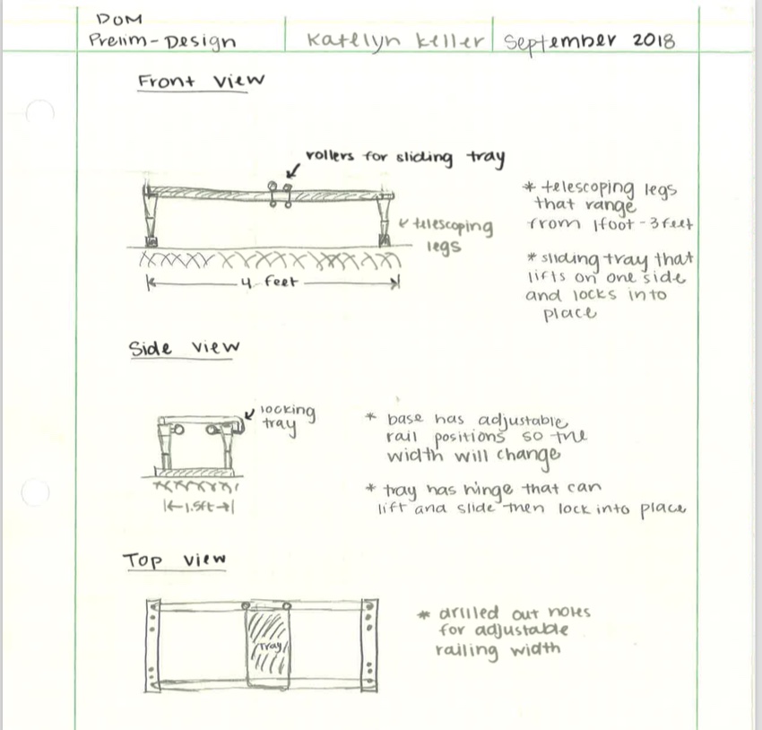
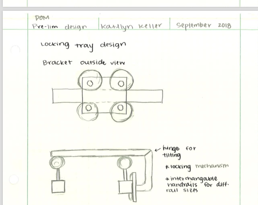
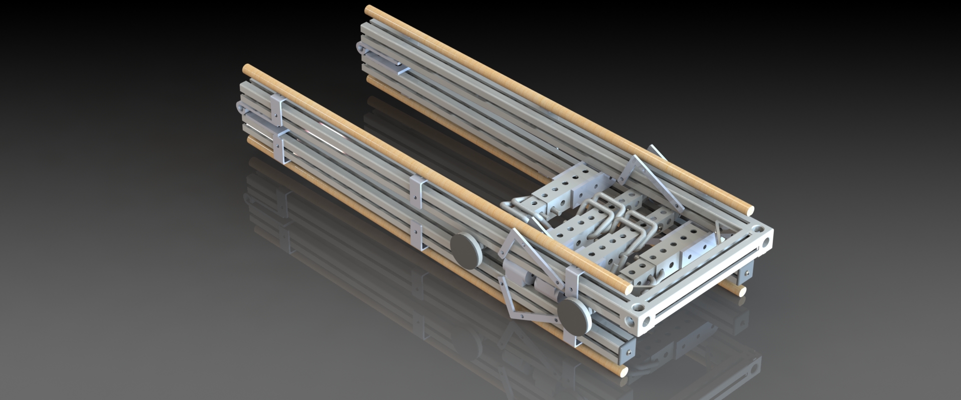
For this design the needs of the mother of the child and how to make the equipment the most efficient was the main priority. The idea was to make the equipment as portable and light as possible so that the mother can easily move and store the equipment with ease. This shows with the easily folding legs and slim design.
Designed By: Katelyn N. Keller
Design Concept 3
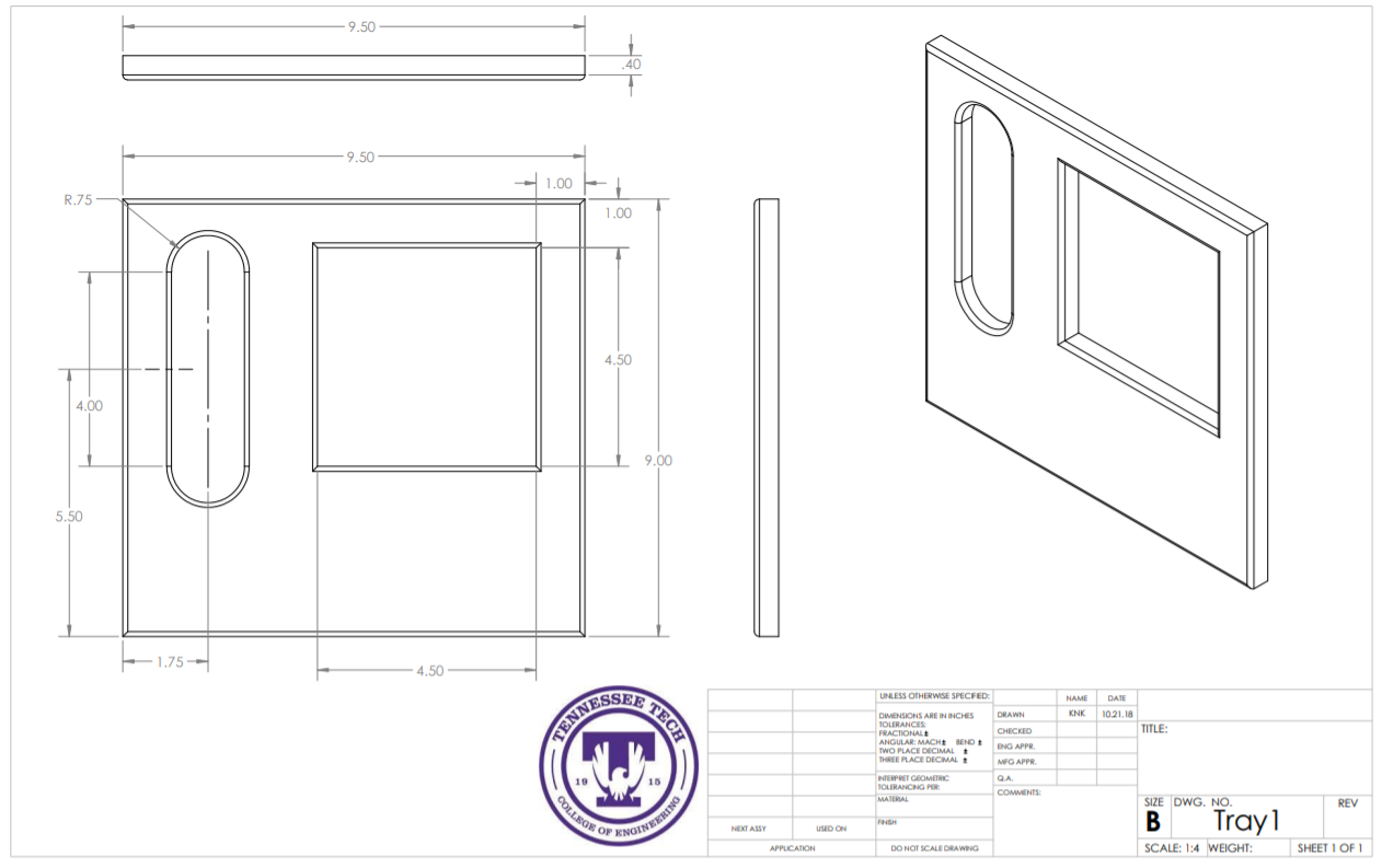
The family that the project revolves around requested for a device which their child can use to practice walking as the child grows. In order to do this, the legs of the device were designed to extend in length so that as the child gets taller, the mechanism can still be used. The width of the device was also designed to extend as needed. Furthermore, a tray was designed for use with the device in order for the child to use it as a support and/or motivation in order to walk.
Designed By: Aaron M. Gross
Design Concept 4
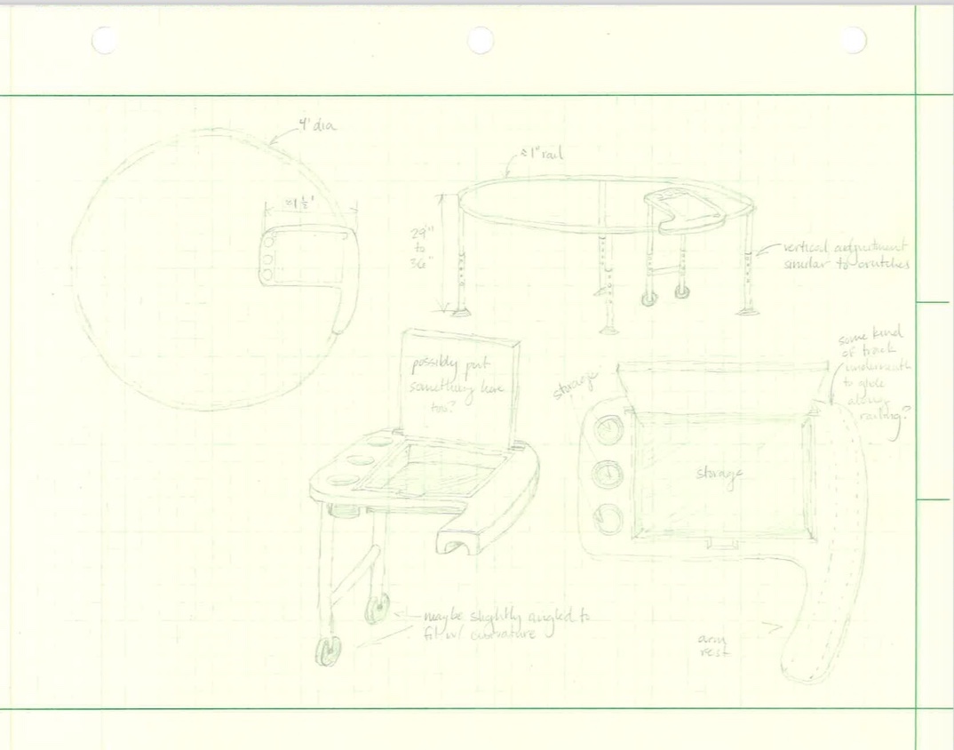
This circular design was brought up as a possibility to eliminate the need to repeatedly change the location of the activity tray. There would be tradeoffs utilizing this alternate approach as it brings machining challenges, however it would make for a constant path of travel and easy monitoring. The tray assembly would roll along the path of the circle, and would be equipped with plenty of storage.
Designed By: Stephanie G. Parnell
Evaluate concepts/select candidate
| Concept Design No. | Mobility | Adjustability | Weight | Cost | Total Points ! |
|---|---|---|---|---|---|
| Design 1 | 4 | 2 | 4 | 3 | 13 |
| Design 2 | 3 | 4 | 3 | 2 | 12 |
| Design 3 | 2 | 4 | 2 | 2 | 10 |
| Design 4 | 1 | 2 | 1 | 1 | 4 |
Detailed Design
This section will describe a detailed design process
Detailed description of selected design
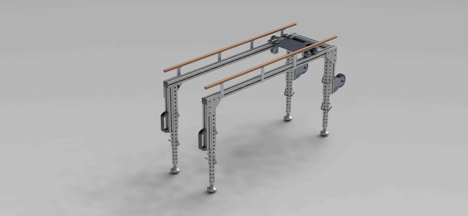
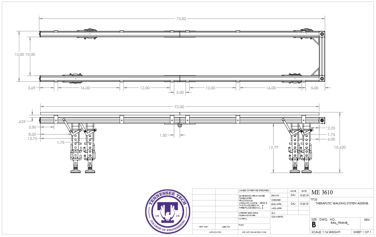
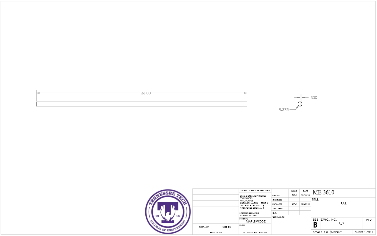
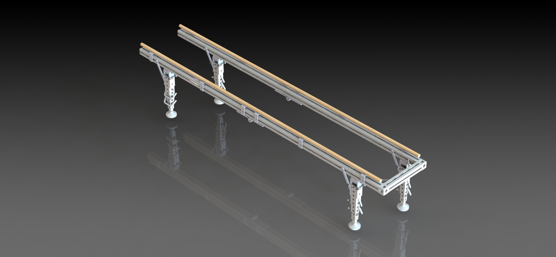
We chose design number one, and considering the comments given, we modified our design for the better. We reduced the weight by 35 pounds while increasing the length by two feet and making it more compact. The entire design is adjustable to the child's growth. The telescoping legs range from 14 inches to 26 inches which is just below the standard height of a physical therapy parallel bars. Given the size and age of the child the system is made for, these dimensions are appropriate. For the width of the mechanism, we plan to provide additional cross members so that the width of the device may be adjusted as needed. The installation of these cross members will be very simple, special tooling will not be required. We also plan to show the family how to do it. The handrails we selected are made of maple and have a fixed diameter of 3/4 inch. To adjust for growth, additional sizes of handrails will be provided. The tray is designed to be interactive and lightweight. It will be plastic with supporting metal beams underneath that can adjust with the system.
Analysis
Engineering analysis 1 will evaluate the total weight of the mechanism. Engineering analysis 2 will analyze vertical loads on the system. Engineering analysis 3 will evaluate deflection of the handrail between two brackets.
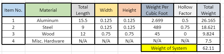
Engineering analysis 1
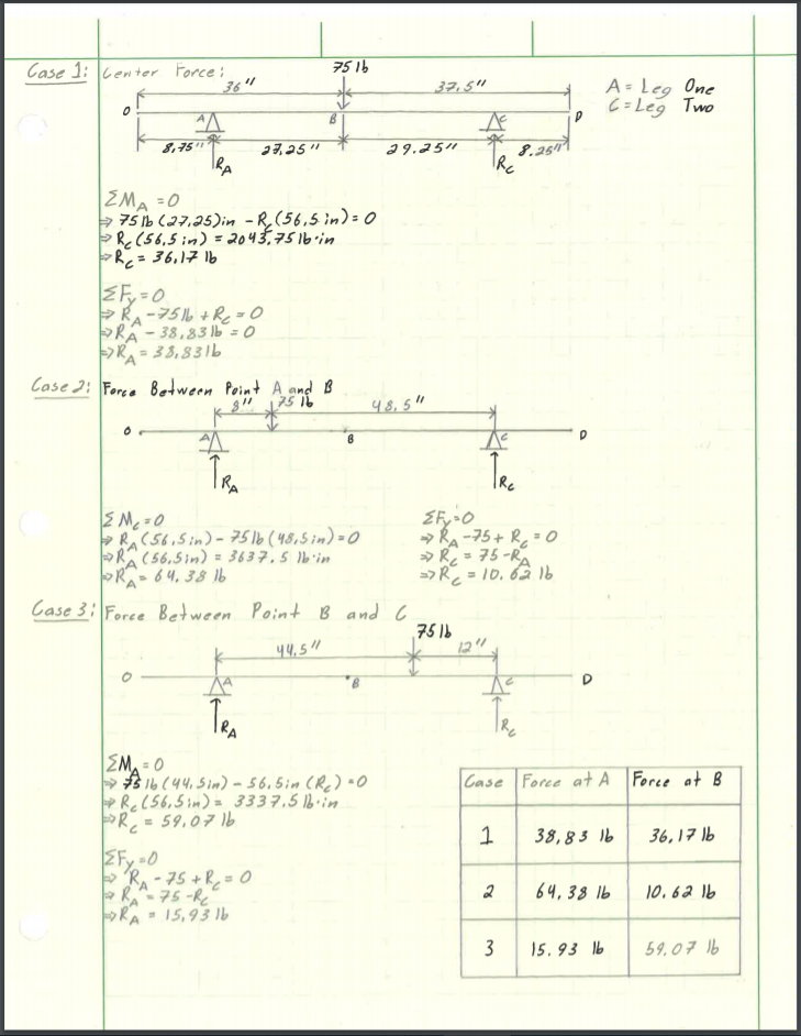
Engineering analysis 2
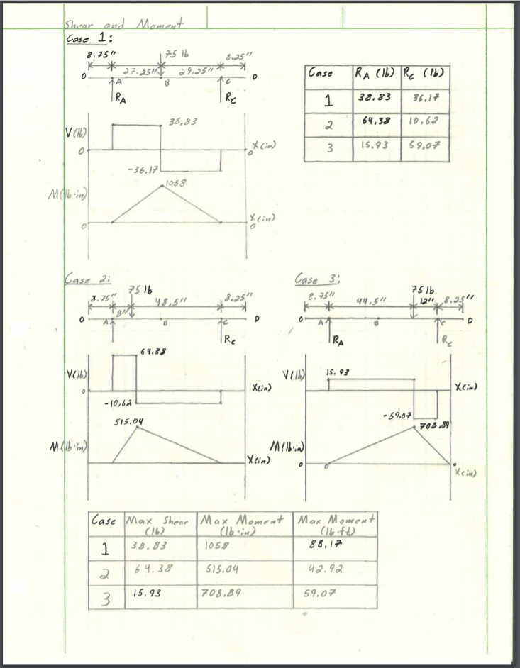
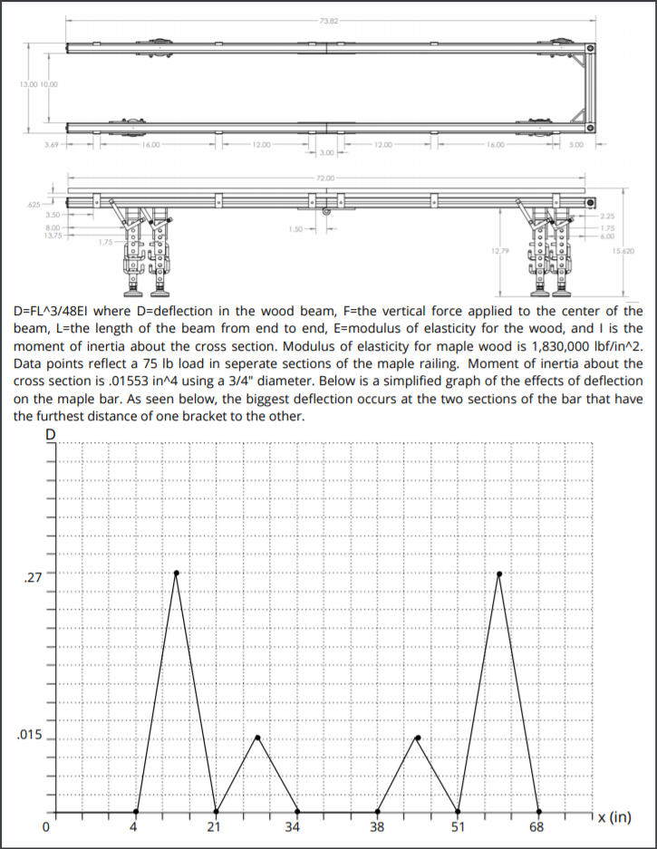
Engineering analysis 3
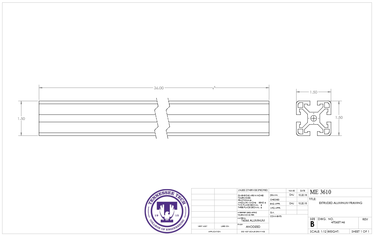
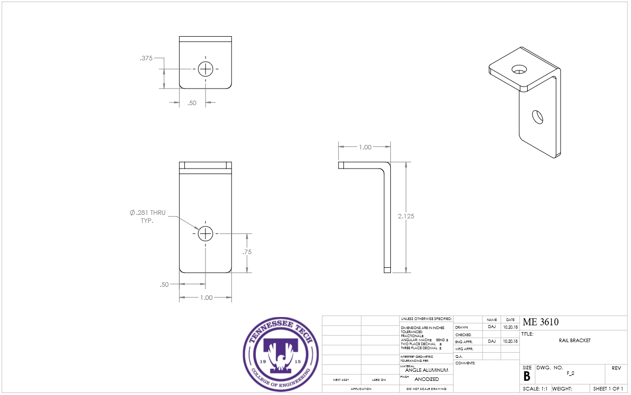
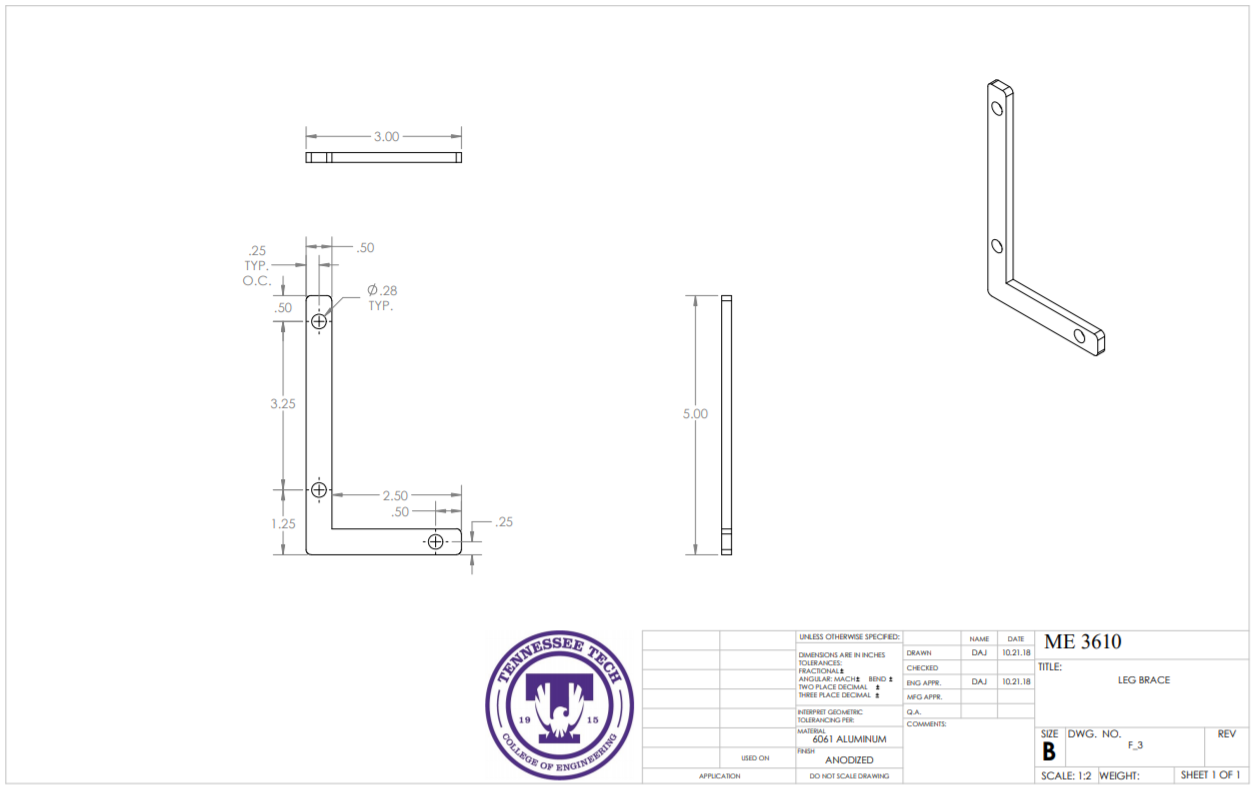
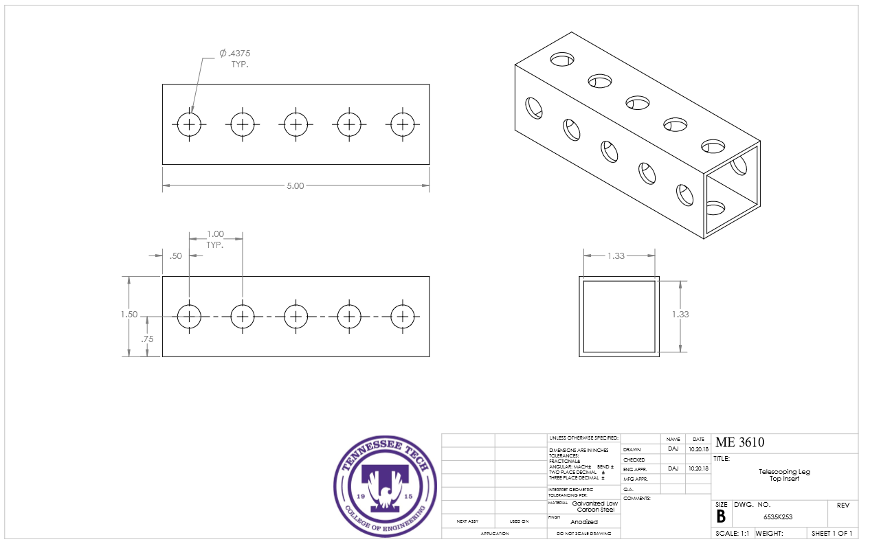
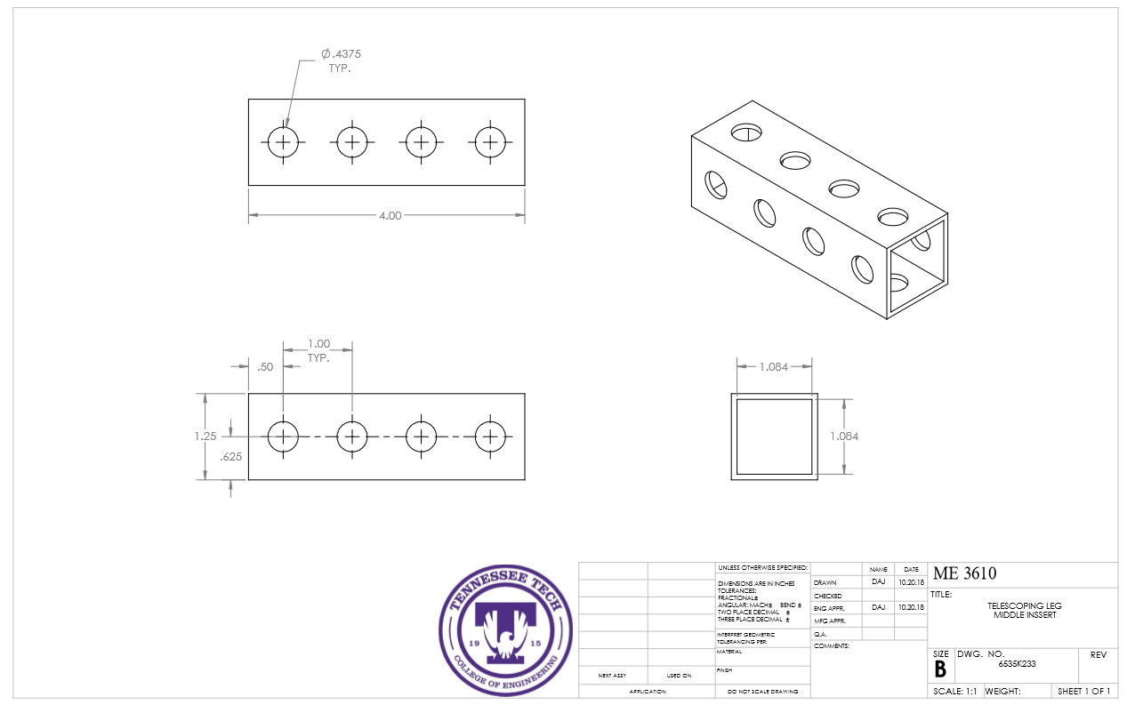
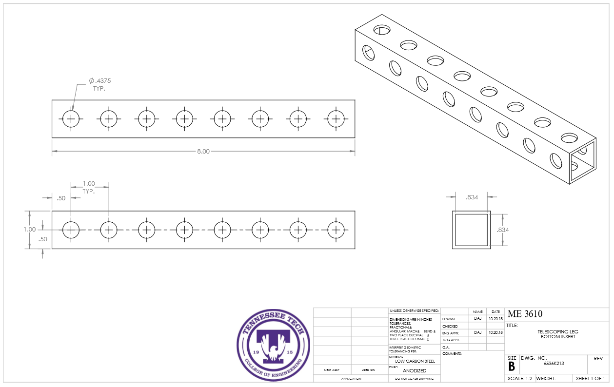
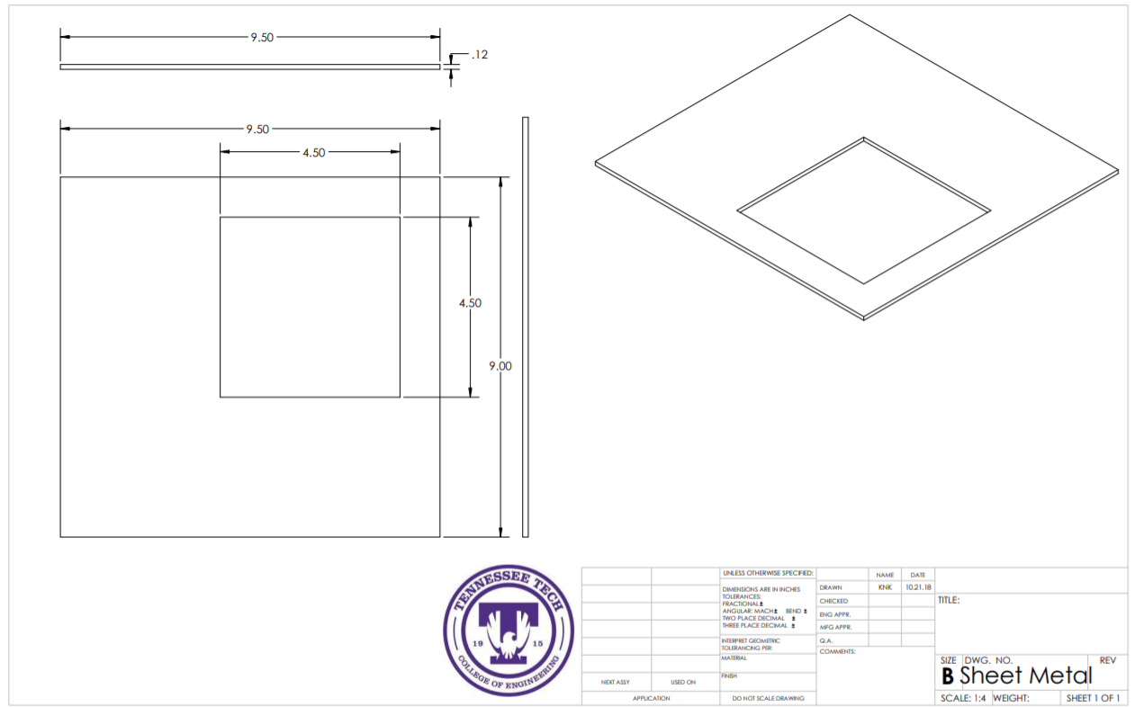
CAD Drawings
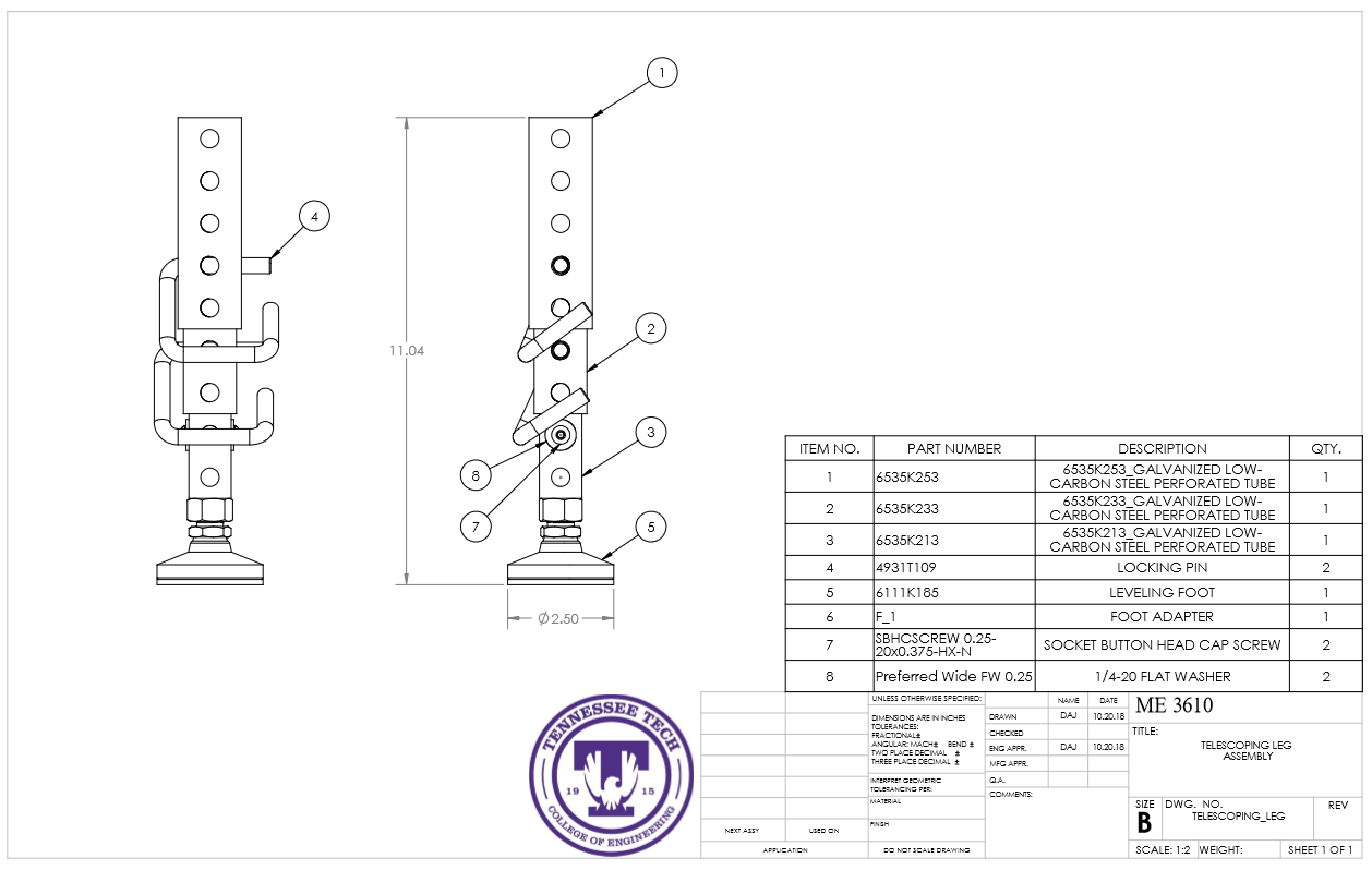
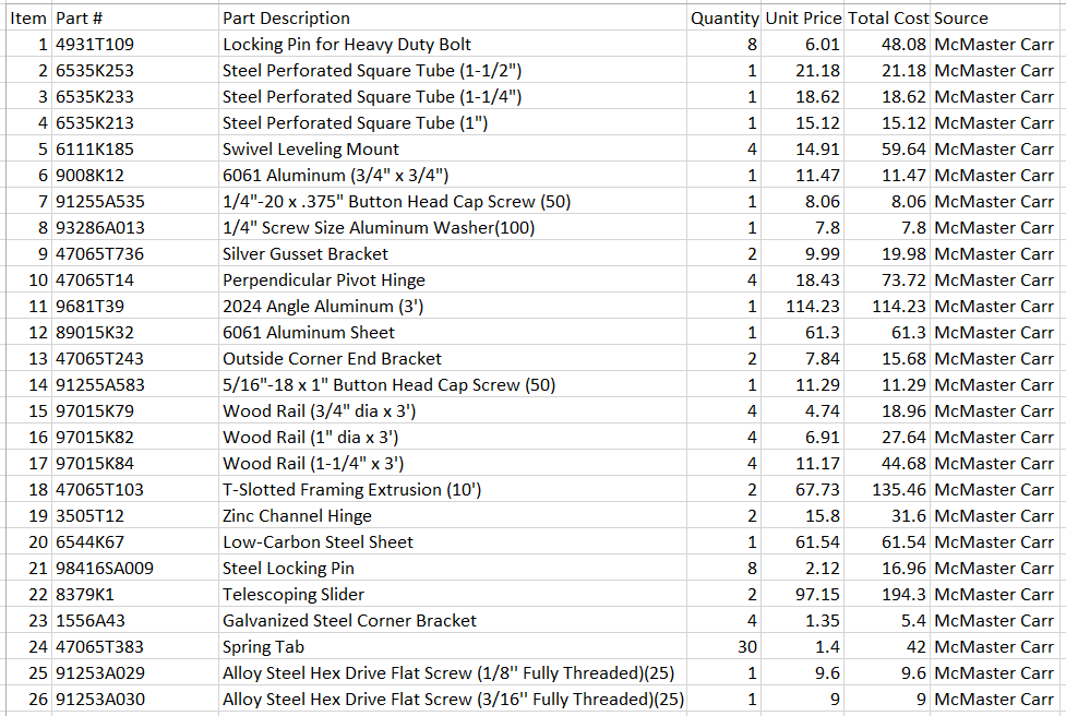
Bill of Materials
Assembly Instructions
Fabrication Process
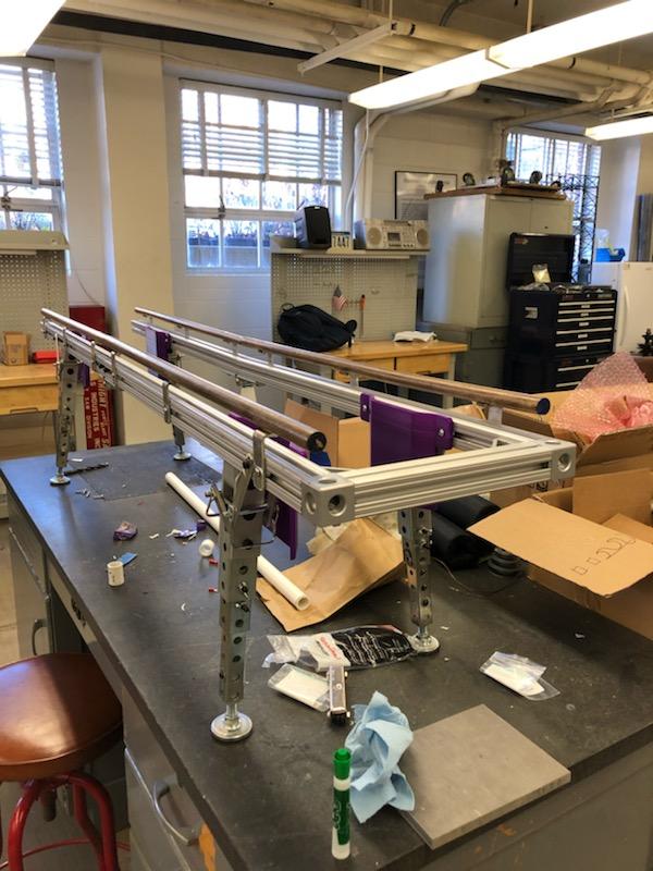
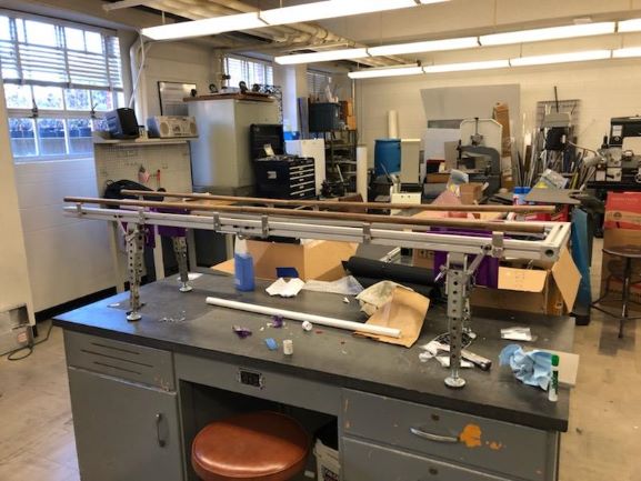
Insert pictures of fabrication process
Step 1 Our initial step in the fabrication process was get our Bill of Materials to the Machine Shop to order. After working closely with Jeff in the shop within one week we had all of our materials and were ready to begin the process.
Step 2 Our next step was to get our cuts so we could begin assembling. Our team quickly began cutting the extruded aluminum, steel telescoping legs, aluminum and steel plates and our angle aluminum all per the build prints shown above.
Step 3 Next, we began tapping our extruded aluminum ends and centers for our junction blocks to meet and our hinges to connect. Then we assemble the extruded aluminum frame with our 5/16-18 bolts and our hinges with a 1/2-13 bolt.
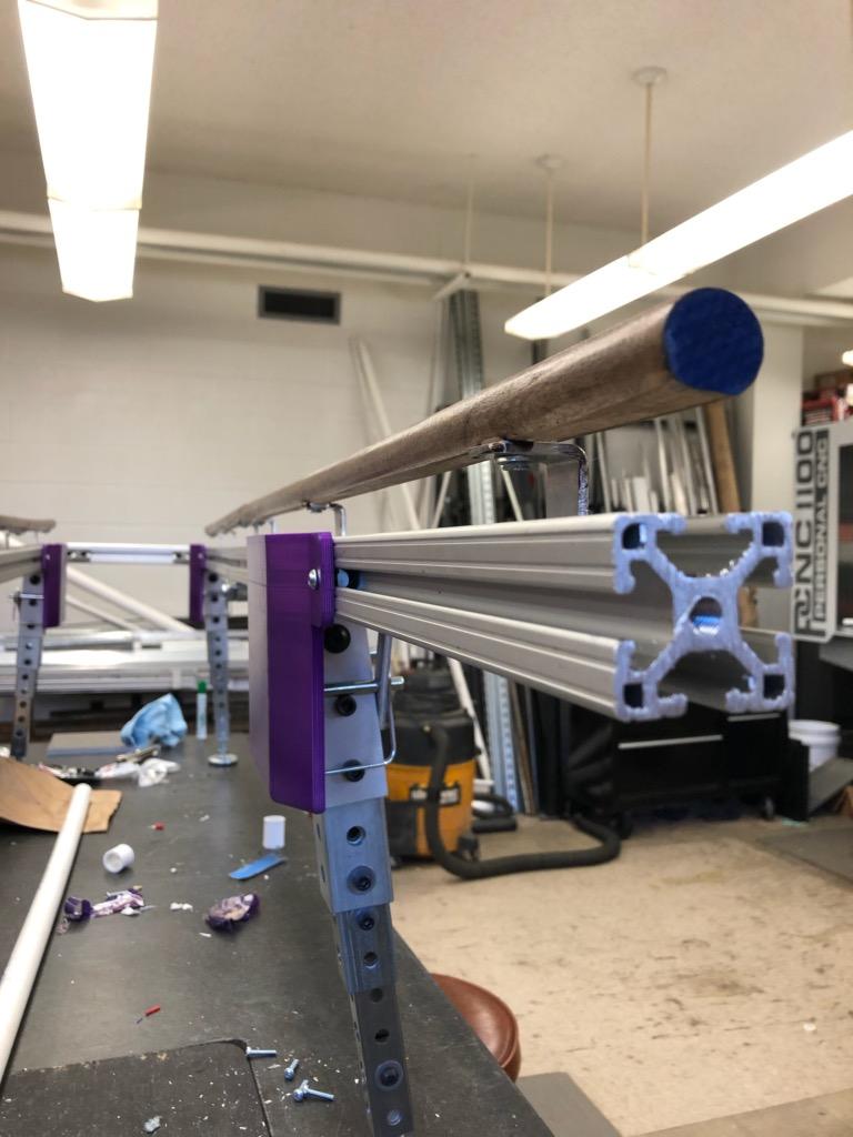
Step 4 Then, while we were individually working on sanding down the rails, fabricating brackets, making the tray, and mounting each of them, the project slowly started coming together. We then ran into the issue of GD&T (Geometric Dimensioning and Tolerancing) where our supplier of the parts were on the high side of their spec, therefore leaving us with telescoping legs that were rather unstable. Quickly we solved the issue by welding washers down the exterior of the center and lower insert and taking out all the play in the legs.
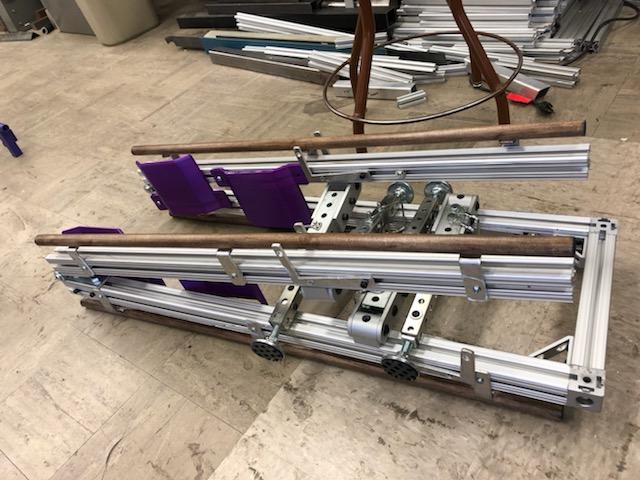
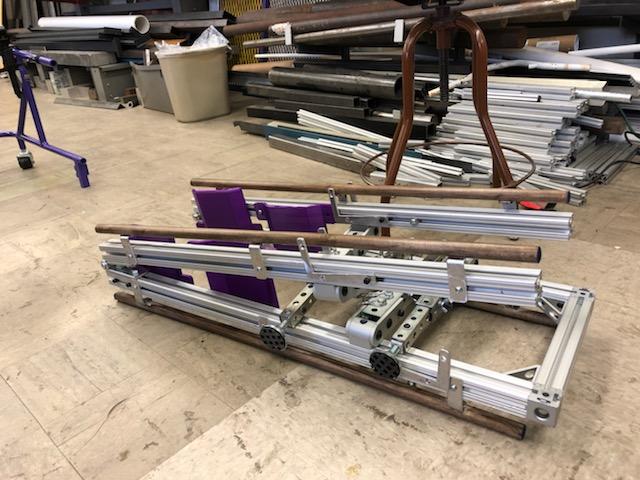
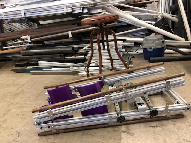
Step 5 Next, we had all the parts ready to assemble. As a team we attached the legs, brackets, hinges, junction blocks, and steel plates all to make the final project come together.
Step 6 Lastly we 3D printed our tray top and protection guards for the entire system and had Dr. Canfield come approve our mechanism. Dr. Canfield went through rigorous testing with us inspecting the stability, weight, accessibility, safety and risk assessment with us. After discussing these topics with Dr. Canfield it was approved to be sent to the family.
Testing and implementation
Testing consisted of multiple methods. Initially when in the design process we ran our model through multiple analysis on Solidworks inspecting the weight of the mechanism, deflection allowed, deflection in the beams, Principle Stress acting upon the main beams and torsion analysis with impulse forces. After meeting a satisfactory level of our design we built our machine. Following the fabrication process Dr. Canfeild and Jeff came and gave us a further inspection talking over safety issues and hands on testing the product to ensure their sanctification.
Photos of Completed design
Instructions for safe use
Do not use the device unless supervised by an adult that has been fully understood the safe use of this product.
Project Summary, Reflection
The design process for the project went well. The group was able to reach a consensus on most topics of discussion easily. All group members were encouraged to provide input during each meeting and often did. During the fabrication process, we ran into a few issues. The most important issue we ran into was that there were issues with the bill of materials. Some of the hardware listed on the bill of materials was wrong, which delayed work on certain areas of the project. There were also a few unaccounted for problems as well. The first being that the self leveling feet, we realized, would not give us the desired results for the project. We had to replace them with normal feet. The second problem was that the hinges that fold the frame had more "freedom of movement" than expected. We resolved this by creating sliding supports to go in the frame. These supports eliminated any horizontal and vertical movement from the hinges. Despite some unaccounted for issues in the fabrication process, the project went well.