Pegasus
Abstract
The purpose of this project is to build a mechanical horse so the child can continue his hippo therapy at home. The previous mechanical horse is too big for the child's house, so the horse needs to able to fit into small spaces.
Team members
- Terrence Sherrrill Gavin Campbell Shelby Dockery Mohammad Tawhari Tolu Oluwalana*
Acknowledge help of others
- Hedi Clopton(The Pediatric Occupational Therapist),Zachary Layne ( Former Tech Student)*
Problem Statement/overview of the need
The young child has difficulty moving around and constantly needs help from his mother. They use to go to horse riding therapy, however, the trip there and back became too difficult.
Design Specifications
1. The horse length needs to be at least 50 inches long for him to lay face-down on the saddle. 2. Needs to be at least 32 inches from the ground 3. Must be able to hold up to 80 pounds
Background research
1. The mechanical horse from last semester, Spring 2020, and a video on Youtube called, "Computational Design Of Mechanical Characters" created by DisneyResearchHub. https://www.youtube.com/watch?v=DfznnKUwywQ&t=186s (at time 2:54-4:35) 2. The availability of the mechanism is very limited due to only having Spring 2020's as a reference. 3. The mechanical horse from Spring 2020 had several missing gaps in the mechanism. One of them was the size of the horse. Another one was the mobility, being able to move it to different locations, and finally the motion of the horse itself.
Conceptual Design
Summarize your conceptual design process. Develop at least three concepts.
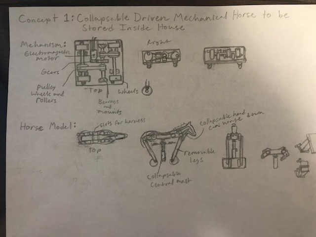
Design Concept 1
- Concept 1 is a small, collapsible mechanical horse driven by an electromagnetic motor and designed to be used and stored within a small interior environment. The mechanism is displayed on the concept drawing and the motion is as follows: the small electromagnetic motor at the middle top of the square is activated and is geared up once to increase torque for the movement, the output gear to this gear up is attached to a splined aluminum shaft with two small diameter pulley rollers on opposite ends of this axel, the small diameter pulleys turn belts which turn a forward and rearward axel with larger diameter pulleys to again increase the torque for the movement of the rollers at the end of the forward and rearward axels. These rollers have a single pivot point at a certain radius from the center and are all timed at different intervals in order to simulate the walking step order of a horse. The mechanism and horse itself will be moved by small rolling wheels on beams below the mechanism box and held stationary by two wooden block stops. Moving up to the "body" of the horse, it has four legs which feature joints attached to the main body as well as hinge joints which attach to the main legs going down to the rollers and connecting to the mechanism. The central support of the body is a collapsible metal support with a spring and plate attaching it to the central beam of the body this set up allows for the legs and rollers to more accurately simulate the motion of the horses legs as they rise and fall when it walks as well as the spring on the main body support and the force from the legs simulating the gentle back and forth sway and bounce of a horse. Over the wooden body will be a layer of soft padding that will cover the body of the horse and both provide soft surface to ride on as well as replicate the body of the horse, over this will be a later of felt or cloth which will act as the fur or skin as will as a soft toy horse head on the front. In an effort to maximize the compact nature of the design, the horse body can have it's legs removed by simply sliding them off their pivots, lowering the central support all the way down, and finally unlatching the head of the horse and hinging it down to lock towards the front legs area of the body. The legs that will be detached are the portions connecting to the roller joints in the mechanism. The primary construction materials in this project will be wood, with aluminum used for most moving parts other than the gears which will likely be steel. The motor will be well ventilated via holes in the mechanism box and can be smaller due to the increased torque provided by the mechanical advantage features of the design. The dashed areas are the areas where bearings will be used in order support the moving elements while allowing them to role. We are unsure what harnesses will specifically be used as of right now so we have simply decided to leave splots on the skin down to the frame for them to be placed in until we get more information.
-
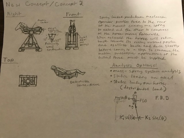
Design Concept 2
This new concept is a spring loaded pendulum mechanism. The operator provides a force to the rear of the mount causing one spring to extend and the other to compress as the horse is moving forward. When the horse is released, it will return to its original resting position and oscillate back and forth until it comes to a complete stop. In order to have continuous motion, successive applications of internal forces must be applied.
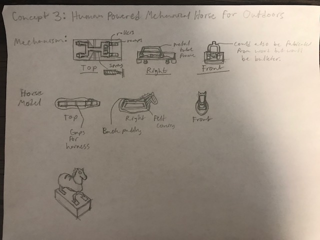
Design Concept 3
- Concept 3 is a manually actuated system with a more simple motion than the previous driven models and is also meant to be outdoors but could potentially be redesigned with featured to make it more compact for an indoors model as well. Unlike the previous two concepts, this one requires someone to first push the horse forward, when pushed forward the rollers and bearings will ascend then roll down small metal tracked hills in the mechanism box simulating the buck of a horse. When this forward displacement occurs it expands a spring which is attached to the forward axel on one end and a beam within the box at the other end. This spring will then contract pulling the horse back over the hills to the starting position where it will be stopped by the padded buffers towards the rear wheels of the horse. Repeating this motion will simulate to some extent the feeling of riding a horse with the movement and hop, however it may be very tiring for the operator. The rolling mechanism may be made out of tubular steel or aluminum depending on resources or could also be constructed from wood. The main body of the horse will be the most simple by far with only a wooden under frame then the padding, felt, and other outward features discussed in previous concepts but not requiring any leg assemblies. The weatherproofing will be a similar method to the shell method in concept 2 but with a smaller box as there is no reason to have the shell extend all the way over the mechanism box. This concept has the most simple mechanism and construction by far but at the cost of being more labor intensive from the operator and a less accurate motion.
Design Matrix
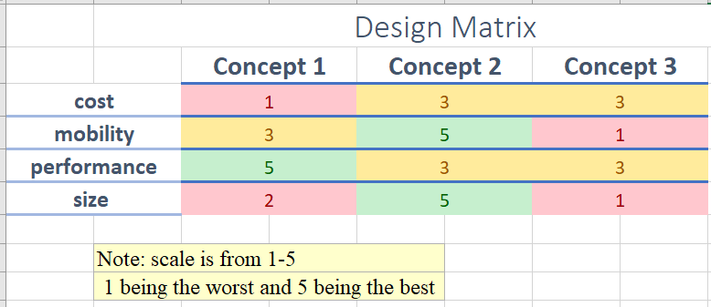
After creating the design matrix, we decided on concept 2. Since, it fits all our criteria the best.
Detailed Design
This section will describe a detailed design process
Description of selected design
We decided to build the spring loaded pendulum mechanism. Since, it will fit into small spaces and give the best mobility.
Detailed description of selected design
Analysis
Describe three types of analysis to be performed on the design
Engineering analysis 1
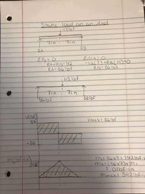
The static load is determining how much force is being applied to a certain object when it is stationary. From the horse and the child's weight, the total amount of force acting on the axel is roughly 112lbf. After calculating the moment and shear diagram on the axel, the shear max turned out to be 56lbf and the max bending moment is 392lbf*in.
Engineering analysis 2
Engineering analysis 3
CAD Drawings
Insert drawings of all parts and the assembly
Bill of Materials
qty, item, description, source, part number, price
Assembly Instructions
Fabrication Process
Insert pictures of fabrication process
Testing and implementation
Describe testing, delivery, how used/received by the family
Photos of Completed design
Insert pictures of the final product
Instructions for safe use
Provide a clear summary of safe use for the family. Do not use the device unless supervised by an adult that has been fully understood the safe use of this product.