Play area control
Contents |
Abstract
The purpose of this project is to aid a family by securing the primary door in an apartment. This family has a toddler that has familiarized herself with how to open the door that goes outside. This has presented a safety concern for the child. As an engineering team, we hope to create a solution that will preserve the safety of the child by keeping her from going outside unattended.
Team members

From left to right: Austin Bowser, Mark Price, Lucas Redden, Daniel Thornton, Matthew McLaughlin
Problem Statement/overview of the need
The details of our project include a family living in a studio apartment where the mother is wheelchair-bound and her child has just learned to walk. While the mother spends her time babysitting, the child is free to run around the house. It has become evident to the family as the child learned to walk that she is fond of going outside, and will do so by opening the front door and escaping without any supervision whatsoever. Due to the mother’s lack of mobility, she worries that when her child is older and able to reach the lock by herself it will become impossible to keep her inside. Our project has been tailored to tackle these problems where modifying the house is not an option as well as dealing with wheelchair compatibility and child safety.
Design Specifications
1. The mother must be able to remotely control the lock on the front door.
2. The servo and the lock must be protected so that the lock cannot be operated, and the servo cannot be damaged by the child.
3. There must be 3 different methods of operating the lock. 2 electrical methods and 1 manual method as a backup.
4. The system should still operate if the main power supply is disconnected. For example: if the power goes out or if the system is unplugged from the wall.
7. A case must be made to protect the control unit.
8. A 3-D printed plate must be affixed to the end of the servo to operate the lock.
Background research
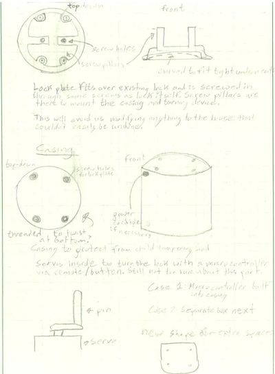
While researching possible solutions we found electronic deadbolts that could be used and are readily available, but since the family is in an apartment this option was ruled out as it would require the locks to be changed. Another option we found is a 3D printed device that goes over the lock and can be electronically controlled by an Arduino. This option seems most ideal as it can be adjusted to meet the needs of the family more easily. The Arduino also allows us to add necessary features that we would otherwise have to rely on being built into an electronic deadbolt. Ideally we will have a device that is as durable and child proof, as well as easily removable and does not change the lock itself.
Conceptual Design
Summarize your conceptual design process. Develop at least three concepts.
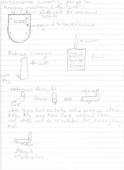
Design Concept 1
This design utilizes a servo with an extended rod to emulate the use of a finger to unlock the door. It features a backup battery that auto-locks when disconnected from the main power outlet as well as a keypad and mechanical failsafe for use in emergency situations.
Design Concept 2
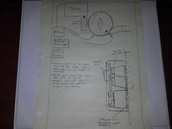
This design features a worm drive for operating the lock, as well as sensors that allow the Arduino to know whether the door is locked or unlocked.
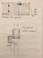
Design Concept 3

This is an aerial view/floor plan of the gate design. The red object is the front door. The yellow object is the coat closet. The orange is the gate. This view shows the clearances each door has in its swing.

This is a side view of the gate plan. It consists of three main components. The yellow is the weighted base (to prevent knocking over the gate/barrier). The green is the uprights of the gate. The red is a roller concept to help deter the child from climbing over the gate/barrier
Evaluate concepts/select candidate

Based on this decision matrix, concept 1 is the leading candidate. This means that we will use this concept as the main foundation for this assembly.
Detailed Design
The design that we have chosen to build on is most similar to that of concept 1. The assembly consists of a servo that directly turns the deadbolt latch using a 3D printed hub component similar to that already previewed. The servo can be controlled by two different methods, radio frequency fob or by entering a code using the 1x4 keypad. Also, the deadbolt can still be operated manually by unlatching the hinged case and revealing the deadbolt. Ideally, this mechanical operation will only be used in case of an emergency. Furthermore, the entire assembly is designed with an aluminum plate as the primary structure. This plate is attached to the door by being constrained between the deadbolt latch and the door slab using the two original screws. Likewise, the case is hinged to this plate.
The electrical components that control and power the servo motor are housed in a separate case that will be mounted on the wall. The battery pack will constantly be charging using power from a wall outlet. The motor and controller are powered from the battery pack, which has a primary voltage output of 5 volts and a secondary voltage outputs of either 12 or 9 volts. This system allows the entire assembly to continue working during a power outage.
Detailed description of selected design
Analysis
Describe three types of analysis to be performed on the design
Engineering analysis 1
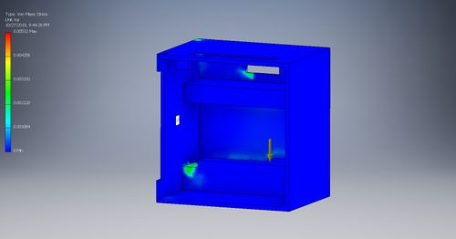
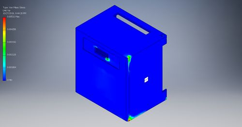
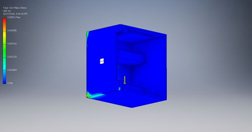
Analysis of the hinged case that will contain the servo and will be covering the lock. This analysis is applying 1/2 lbf where our servo would be, and constraining the case where it would attach to the hinge. The material is ABS plastic, and using the Von Mises Stress analysis the highest stress concentration is only 0.005 ksi. With ABS plastic having a tensile strength of 3.75 ksi, the case is more than strong enough.
Engineering analysis 2
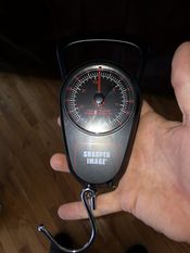
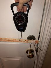
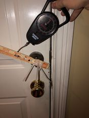
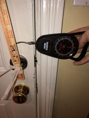
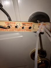
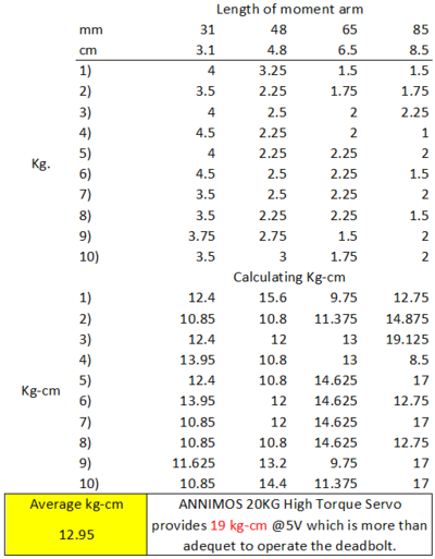
This testing setup is rudimentary, but effective in its role to give our group a better understanding of the amount of torque to successfully actuate a deadbolt lock. The setup included: an exact copy of the lock the family currently has installed in their apartment, a spring scale to measure the force, a rigid moment arm with specified distances from the axis of rotation, and zip-ties to adequality attach the moment arm to the deadbolt knob. Measurements were taken ten times at four different known lengths from the axis of rotation. This data was collected and analyzed using excel to calculate the average torque that was required to operate the deadbolt lock. The average required torque is 12.95 kg-cm and the servo we have spec’d provides 19 kg-cm at 5V. There is room to decrease the amount of torque required, doing so would decrease the work of the servo and decrease the stresses on the servo case. Some methods to decrease the torque required would be: properly lubricating the moving components of the deadbolt assembly and/or adjusting the amount the door is pressed against the weather stripping (a tighter pressing door to the weather stripping would better align the deadbolt to the deadbolt strike plate).
Engineering analysis 3
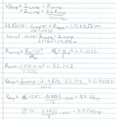
Calculate the voltage drop given worst case scenarios, and compare the drop to the overall loss percentage for 9V and 12V.
CAD Drawings
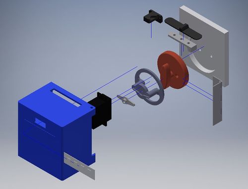 This is an exploded view of the servo case assembly.
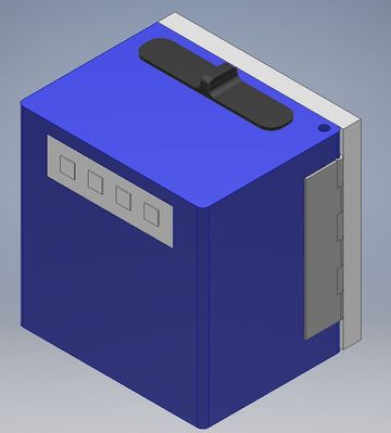 This is a view of the case closed.
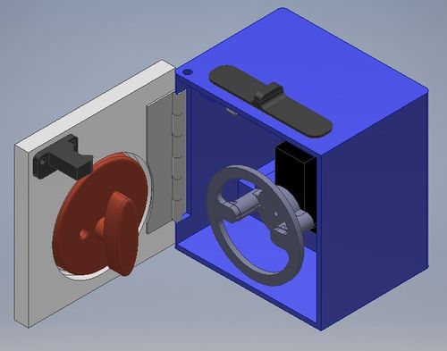 This is what the inside of the servo case looks like.
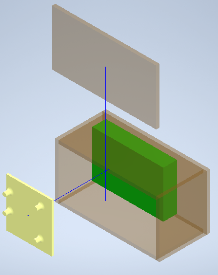
 This case houses the battery pack and the servo controller.
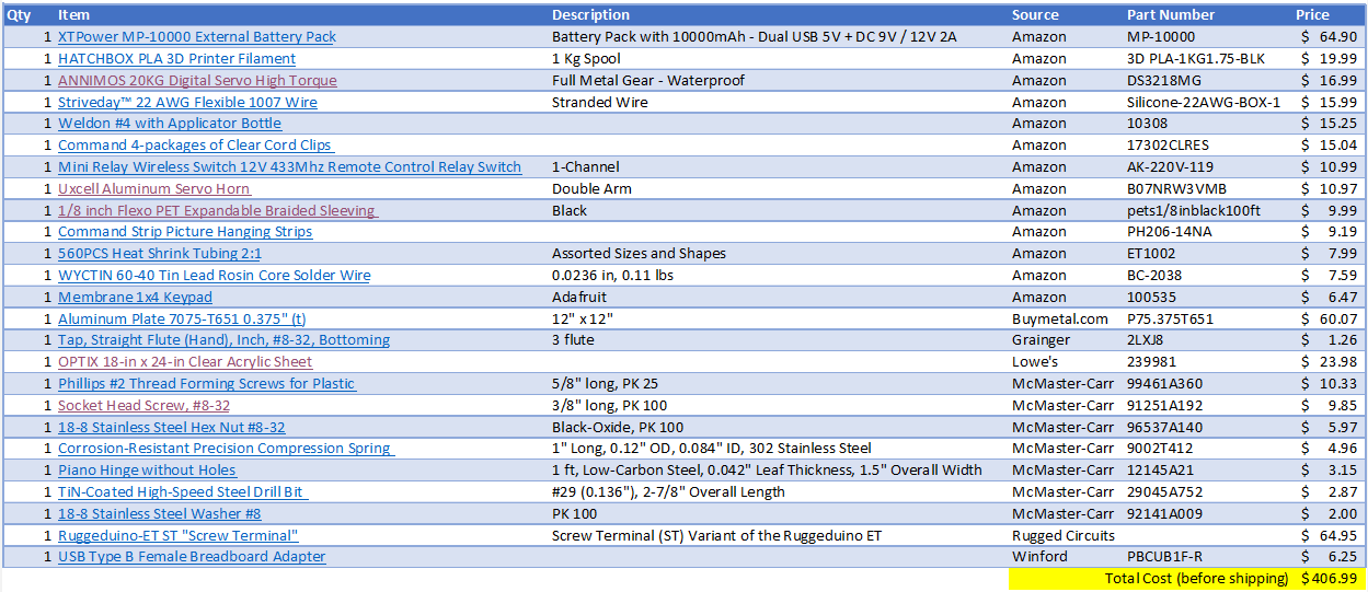
Bill of Materials
Assembly Instructions
Fabrication Process
Insert pictures of fabrication process
Testing and implementation
Describe testing, delivery, how used/received by the family
Photos of Completed design
Insert pictures of the final product
Instructions for safe use
Provide a clear summary of safe use for the family. Do not use the device unless supervised by an adult that has been fully understood the safe use of this product.