Portable Ramp
Abstract
A family has declared a need for a portable ramp that can be used to assist their son when entering their house and car. The ramp will need to be capable of being walked on simultaneously with devices such as a stroller, a walker, and potentially a wheelchair. Structural integrity will be of the utmost importance. However, portability, ease of use, and weight will be heavily considered to make the product as useful as possible.
Team members

- From Left to Right: Charlie Coen, Jadon Kaercher, Devin Roland, Joshua Gaston
Problem Statement/overview of the need
The current market has portable ramps available for purchase that can be used to transport someone up a slope. However, these ramps are not as versatile as our client would like. They are requesting a ramp that can be used for a variety of applications in diverse settings in order to fit their needs and preference. The ramp will be used for both stair ascent and vehicle entry. The ramp will need to be walked on and used with a variety of devices such as a wheelchair, stroller, or walker. The product would need to be adaptable for any possible alterations in venue deployment such as different vehicles, and wide enough to account for other uses such as other equipment that could potentially accompany the client in transport. Space for deployment off the ramp is limited to an extent such that the ramp would not have appropriate space to extend to a distance that would allow for an ideal slope, but the incline should still be gradual enough for the toddler to traverse up the ramp independently after becoming more developed.
Design Specifications
- First and foremost, the product must be versatile such that it can be easily operated at multiple locations, including a mid-sized vehicle and a small set of stairs.
- The product must be able to exist in a compact state such that it could be easily stored in a vehicle or garage when not in use, and must not be designed to occupy unreasonably large space when fully extended.
- The product will need to be constructed in such a manner that the operator can easily and quickly set up the product before use, and collapse equally as effectively after use.
- The product should ideally not be unreasonably heavy to allow for accessible transportation to and from operating locations, and should be considered to be resistant to certain weather conditions such as heavy precipitation.
Background research
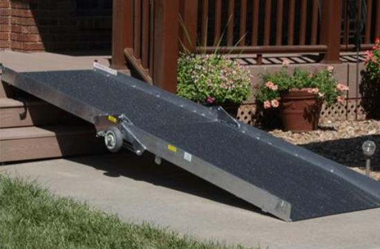
There are several examples of portable ramps for sale we were able to identify. The image provided below is an example of a two-member ramp that includes an anti-slip surface to provide higher traction and is able to be stored vertically after folding in two.
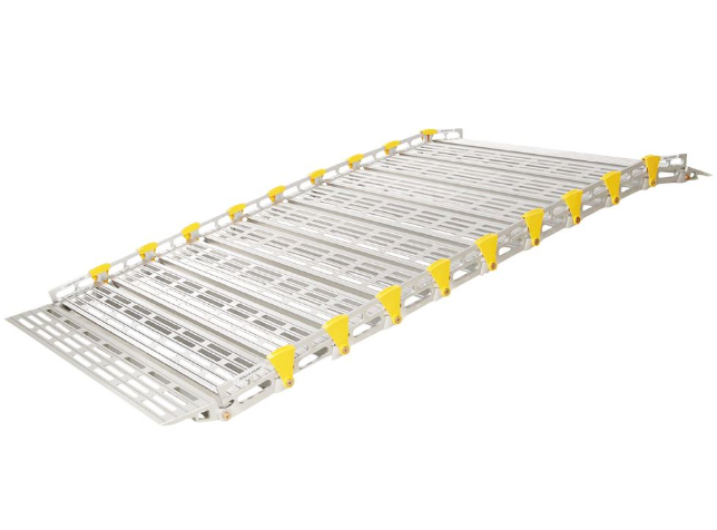
The image provided below is an example of an aluminum ramp that is able to roll up to dramatically reduce its footprint during storage. The profile of the ramp appears to be flexible enough to provide some curvature at the upper and lower ends of the ramp to facilitate a better transition from surrounding surfaces but does not appear to affect the load-bearing capabilities of the ramp.
There are several very similar examples to both of these designs but considerations of cost, adjustability for multiple locations, and total length of ramp surface seem to be limitations of these examples that required for the client to pursue other solutions than purchasing an easily accessible existing example.
Notable shortcomings of these observed designs include a combination of lack of location versatility, total surface length, reductions in storage space, and lack of adaptability for multiple devices.
Conceptual Design
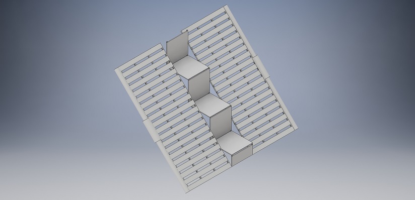
Design Concept 1
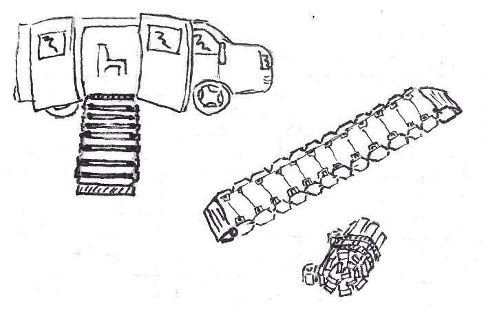
Two mirroring sets of individual, closely fitting plates connected by joints run along the slope of the ramp and sandwich a set of stairs aligned parallel to the plates. Each face of a stair is jointed to the next and stairs themselves are joined to a plate at the forward most peak point of each stair. The series of plates and the segment of stairs is fixed to a long beam at the top and bottom of the assembly. The top and bottom beams are joined by arms that are fixed together by a spring loaded slider that can be adjusted to being breaking down the assembly for storage. Each plate folds back against consecutive plates forming an accordion-like structure, as do the faces of the stairs. The structure will rest on the upper and lower points of contact so that the total length of the surface will remain unchanged during operation.
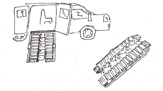
Design Concept 2
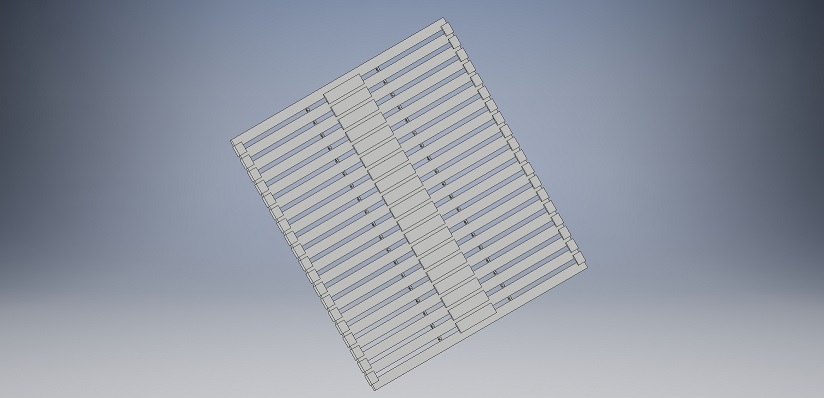
A series of closely fitting plates that measure the full width of the ramp, extends up the slope of the ramp. Plates are joined to one another in the same direction, allowing the assembly to wrap about itself with the traveled surface of the ramp acting as the exterior of the roll. Along the edges of the plates, one-sided brackets are spanned across the top surface of the two plates and welded to only one of the two. A similar but larger set of brackets are mirrored along the center of the plates to further enforce the assembly. The collection of brackets prevent the series of plates from buckling inwards and allow the assembly to wrap about itself outside of operation.
The structure will rest on the upper and lower points of contact so that the total length of the surface will remain unchanged during operation.
Design Concept 3
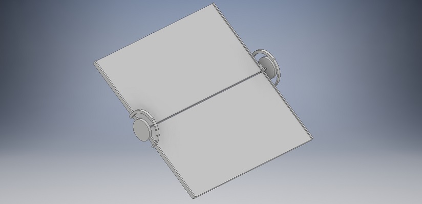
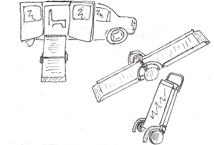
Two large sheets join to extend the full length of the ramp and each sheet measures the full width of the ramp. The sheets are hinged together to permit rotation opposite from what would be induced by the load supported by the ramp, and are fixed to circular tracks along the exterior of the surface that will lock to fix the angle between the sheets once fully extended. The circular tracks extended beyond a set of two wheels that would allow the ramp to be rolled to a location for storage outside of operation and are joined to the hinges that connect the sheets.
Evaluate concepts/select candidate
Design concepts were evaluated against a collection of criteria to determine the most promising design concept to further pursue. Criteria was weighted by importance and each criteria was numerically evaluated on a scale. Less important criteria was judged from one to ten, moderately important criteria was evaluated from one to ten and weighted twice, and highly important criteria was evaluated from one to ten and weighted three times.
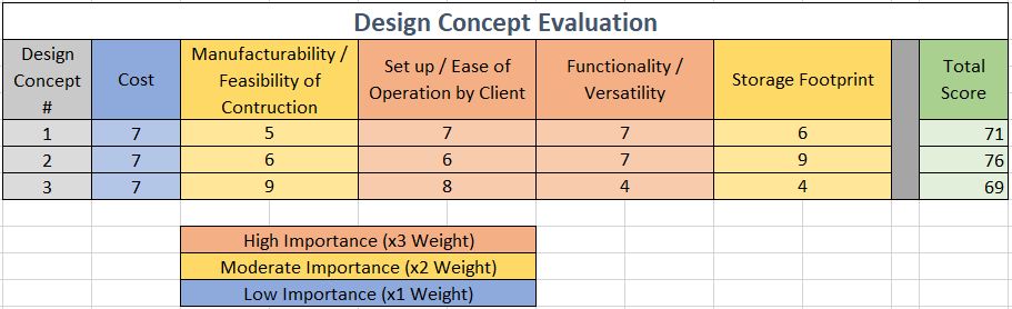
Despite marginally losing to the other proposed designs in an area selected as highly important to consider four our final submission, we are convinced that this would be the most beneficial design for us to seriously pursue. Design two offers a admirable combination low storage footprint, high versatility in locations it can be deployed, and our perceived ability to physically manufacture such a design is still attainable for our skill sets, all without notably compromising our client's ability to effectively take down and set up the product. We are entirely confident the client will be able to efficiently set up the product and are comfortable moving forward with this design selection.
Detailed Design
This section will describe a detailed design process
Description of selected design
Detailed description of selected design
Analysis
Describe three types of analysis to be performed on the design
Engineering analysis 1
Engineering analysis 2
Engineering analysis 3
CAD Drawings
Insert drawings of all parts and the assembly
Bill of Materials
qty, item, description, source, part number, price
Assembly Instructions
Fabrication Process
Insert pictures of fabrication process
Testing and implementation
Describe testing, delivery, how used/received by the family
Photos of Completed design
Insert pictures of the final product
Instructions for safe use
Provide a clear summary of safe use for the family. Do not use the device unless supervised by an adult that has been fully understood the safe use of this product.