Secure Position Child Swing
Contents |
Abstract
Abstract here - a short statement of the need, findings of project and project outcome. For this project our team must design and build a swing for a child with limited mobility. This device must be able to support the child safely in multiple positions while swinging in varies directions.
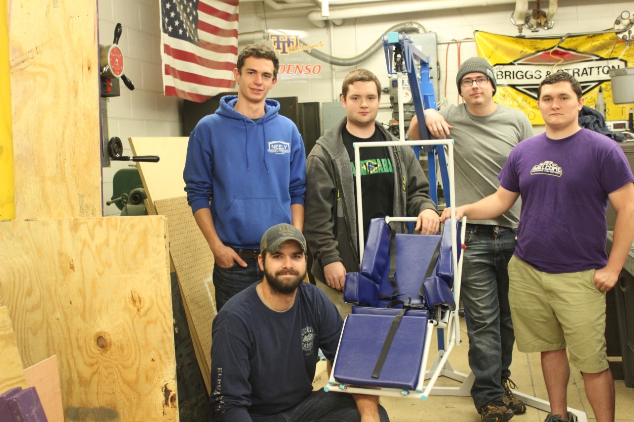
Team members

- Tyler Rice, Daniel Hott, Wesley Gothard, William Alston, Seth Williams
Acknowledge help of others
- other
Problem Statement/overview of the need
Summary of the project need This project will require us to create a suspended chair in which a child with limited mobility will be able to sit comfortable and swing. Also a support/hanging mechanism will be required to hold the child off the ground and restrain the swinging motion to a safe area. This design should allow the parent to secure the child in the swing and work with out having to worry about the child's safety. Developing this swing would hopefully assist in solving some of the daily problems the child and parents face.
Design Specifications
- Support a minimum of 50-100 lbs
- Tailored for a child approximately 36-48 inches long
- light weight and portable
- multi-position
- easy operation
- Tailored to the medical needs of the child
- Variable swinging directions
Background research
http://www.rehabmart.com/category/Pediatric_Swings_and_Swing_Frames.htm The website above lists many swings developed for children with limited mobility along with where to find them and the prices. Most of the swings seem pretty easy to buy but there are some draw backs or gaps in the designs that exist. 1. A lot of the swings are very expensive. 2. If not expensive they are very simple and do not cover all cases. 3. Some are very large and need excess space while others fit in smaller spaces but do not provide as many options or as much support required for some children. Altogether their are swings available but they do not address all the basis for children with special mobility needs or create other problem such as space or storage.
Conceptual Design
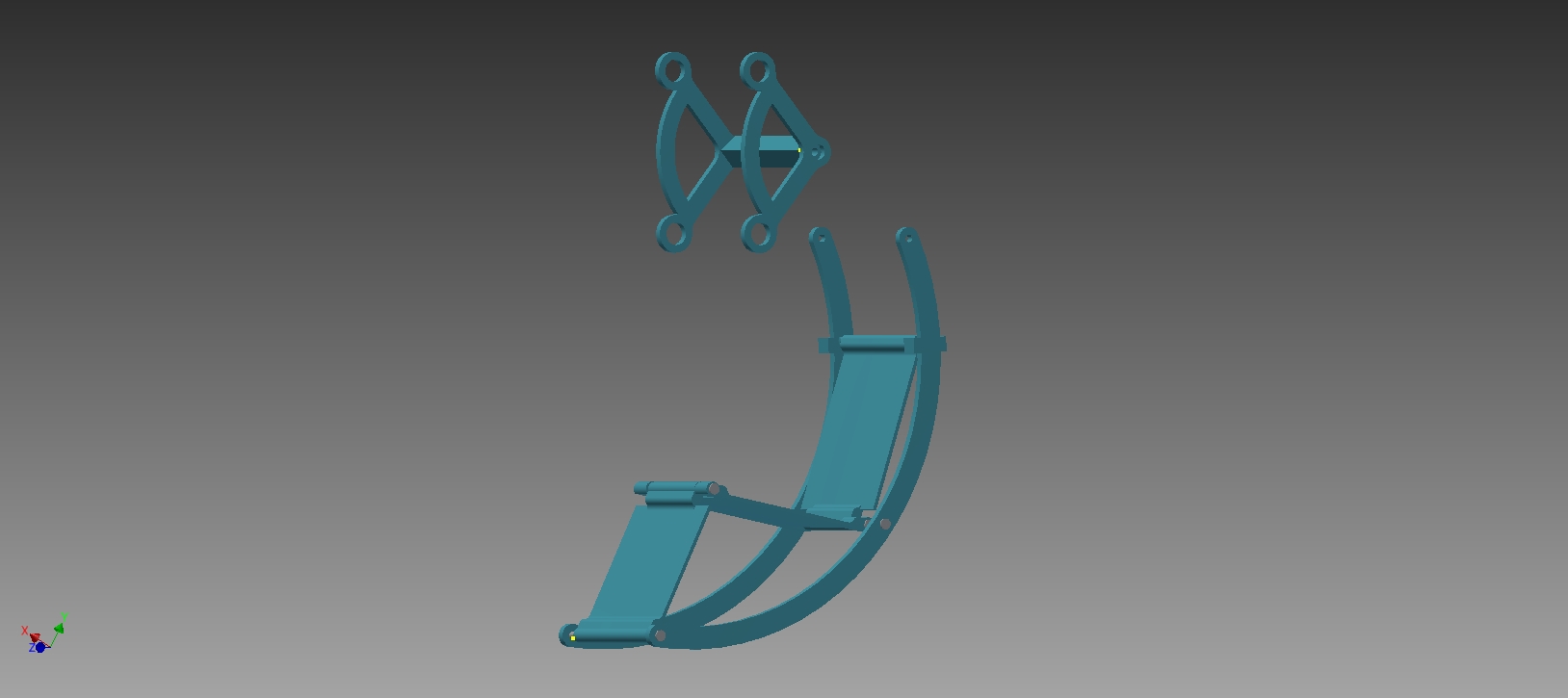
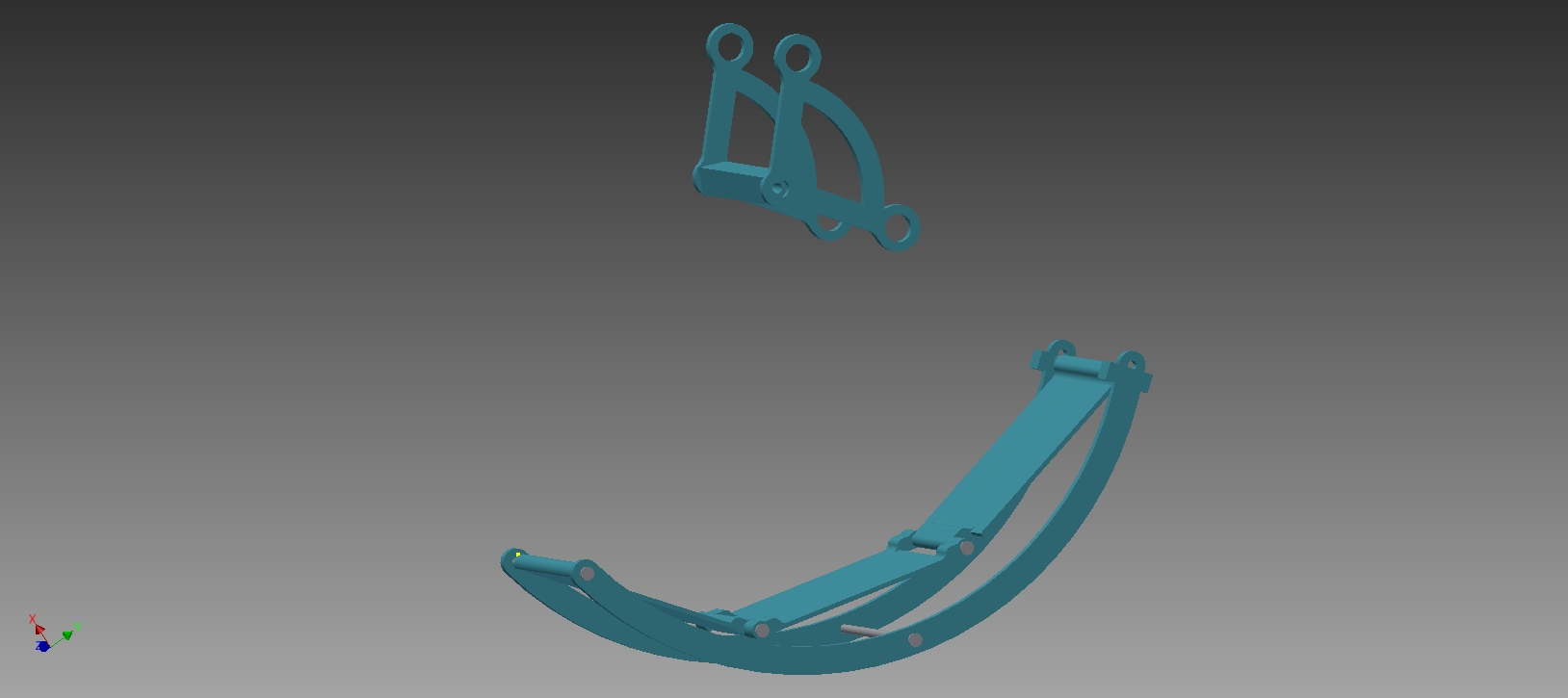
Design Concept 1
- Description
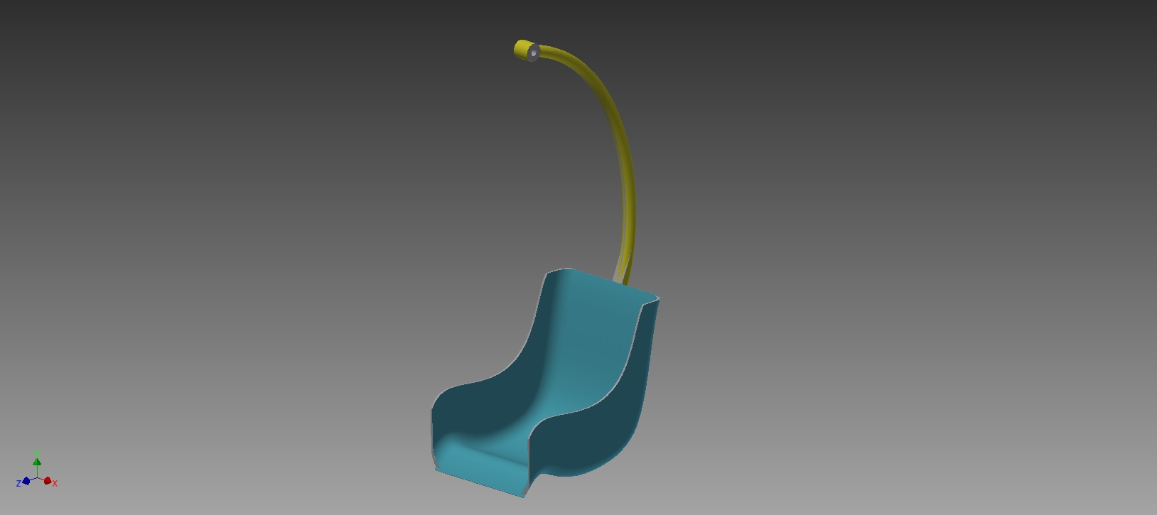
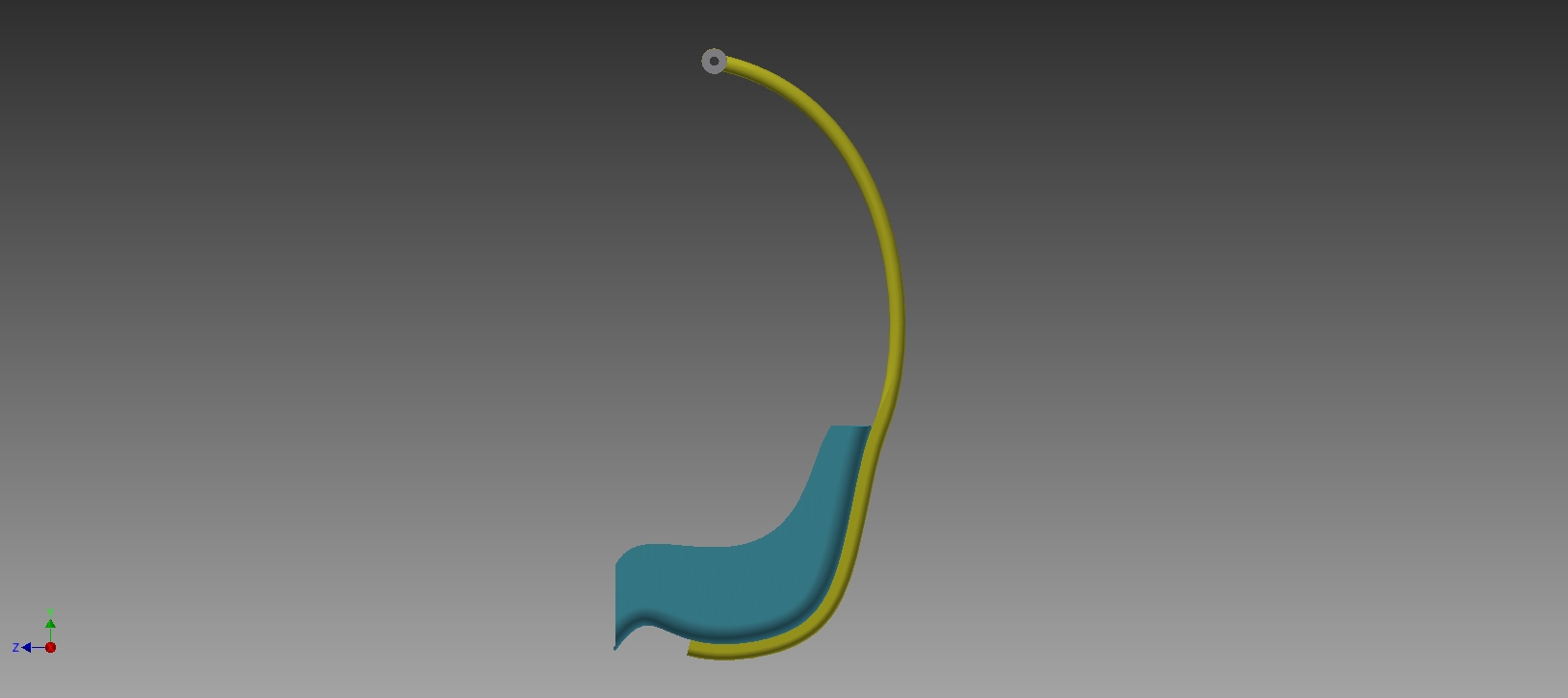
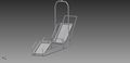
This is a multi- position supportive swing. The lower, seat, and back frames slide along the curved rail and lock into one of numerous positions to transition from a sitting to a laying position while the cam hangers allow the curved base frame to recline.
Benefits:
- Easily convert from sitting to reclined positions.
- Low parts count, and robust design
- Very adjustable for comfort and support
- Easily adapted for maximum safety
Drawbacks:
- More complex design complicates construction process
- More complex design could be cumbersome to move
- More expensive to construct than the other concepts
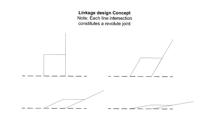
Design Concept 2
- General Description
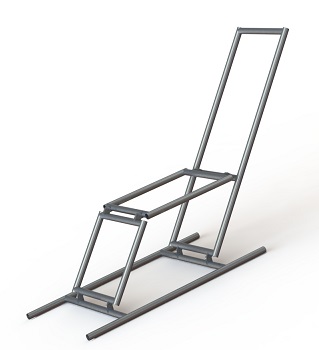
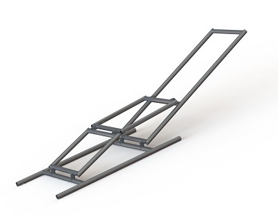
This design concept focuses purely on the usage of linkages. More specifically, the linkages (three in total) will be arranged in a specific geometry to allow the desired motion for the chair. These linkages will be simple rectangular frames when viewed in three dimensions.
- Drawings
- Pictures
- Performance
This design has several advantages, including:
- Simple fabrication and assembly
- Variation of linkage geometry allows virtually any motion desired
- Has a mobility of one, so a single mechanism can lock chair in place
- Tubular frame provides easy mounting to swing mechanism
- Can be stored and transported as a compact package
- Could be easily motorized to change seating positions
- Rectangular frames provide easy mounting of seating surface and cushioning
The disadvantages include:
- This concept is not especially cheap
- May be heavier than other designs
Design Concept 3
- This simple design allows for a safe seating position while allowing the child to swing
Benefits:
- Simple design ensures product delivery
- light weight
- More open design helps in accessing the child and clearing any medical equipment
- Low cost
Drawbacks:
- only swings back and forth
- seat itself is fixed in position
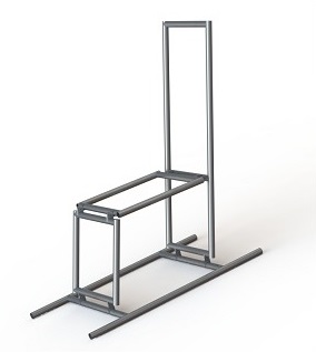
Frame Concept
Design 1
Design 2
Design 3
Evaluate concepts/select candidate
Use a decision matrix or similar tool to compare designs against project specifications Discuss winning candidate
Rating each design from 1 to 5 in each category.
- 1=Very Low
- 2=Low
- 3=Moderate
- 4=High
- 5=Very High
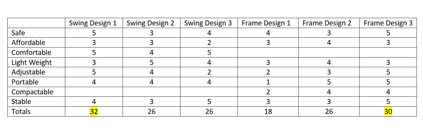
Our Swing design 1 and Frame Design 3 had the highest overall Scores so we decided that would be the combination to move forward with.
Detailed Design
This section will describe a detailed design process.
The first step in the design project was to meet with the client's therapist and the client themselves. After meeting with them we came to an idea of what safety designs needed to be included, how accessible the chair needs to be, and how they want the frame to exactly work. We then started to design some concepts and ideas for both the frame and chair that we want to use. The main point for the chair is that the chair needs to have multiple positions and that the frame needs to be easily accessible.The next step in the design process was forming concepts for the chair.
First, we wanted to figure out if we wanted the chair to be electrically powered, purely mechanical, or a mixture of both. After talking with the client's therapist we came to consensus that a mechanical chair needs to be designed for the easiest accessibility and movement. We then went into the design stage by drawing out full scale models, what material needed to be used, using 3D-modeling technology, and factors of safety that needed to be included. Taking into account the time frame given, we came up with three basic designs and tested and analytically looks at safety factors of each.
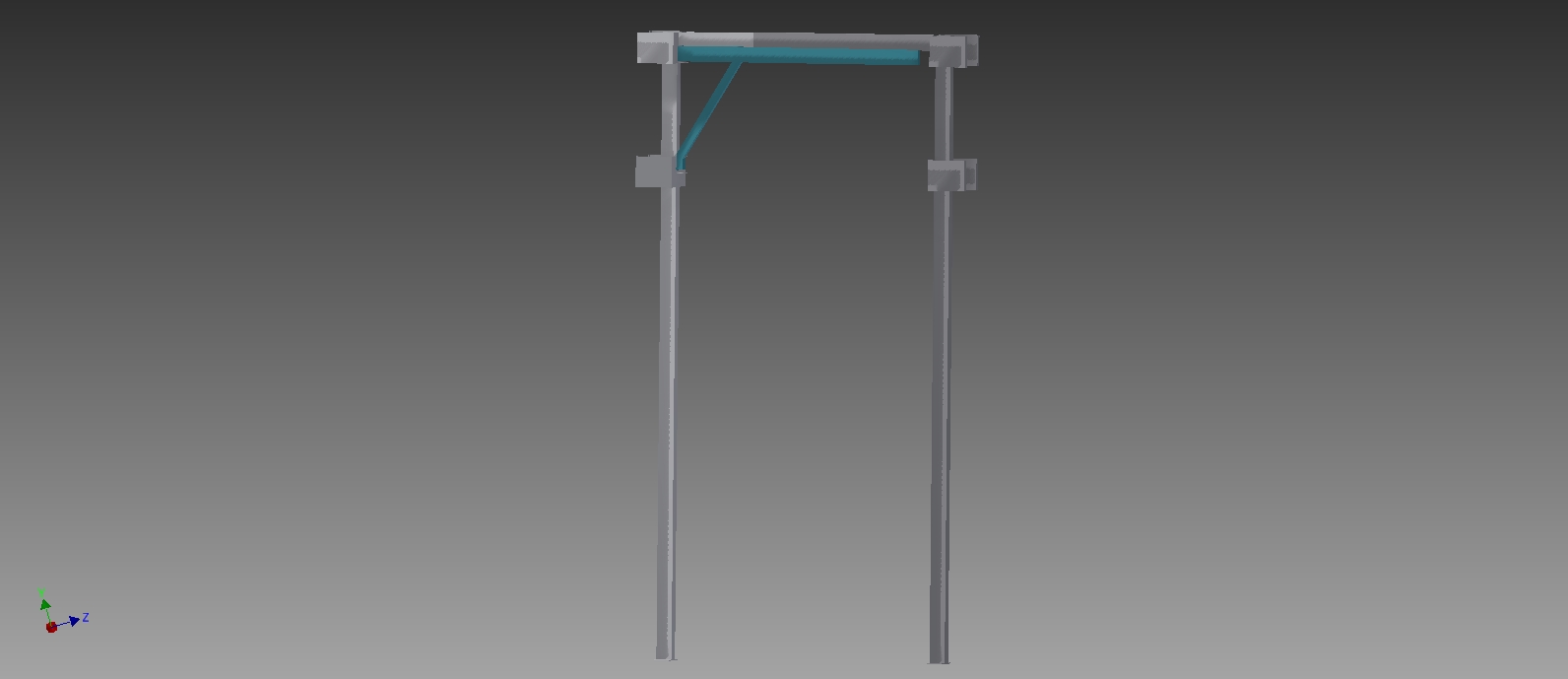
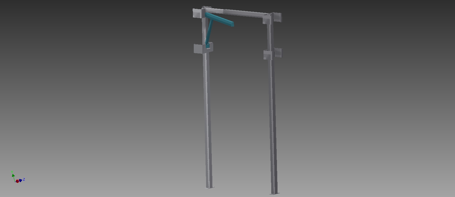
Lastly, the frame mount for the chair. The first thing that needed to be decided was what material we need to use. This is an important factor because the frame and chair has to be light enough to be moved to multiple locations easily. At first, the first design for the frame was a ceiling mount because the client wants the chair to swing in the X,Z, and theta directions and was not sure if they wanted to move the swing or not. After figuring out some factors that would hinder us from being able to do this we then moved to either a door frame mount or a corner wall mount. The door frame mount would still allow for X and Z movement but would restrict theta movement. The corner wall mount will allow X,Z, and theta movements and will take away a degree of freedom so that the frame will not have to be supported from the back.
Description of selected design
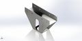
selective position chair-- This chair will allow freedom to be maneuvered as needed for the client. It has multiple positions that it will be able to be changed to with ease. The design will include safety factors to insure the clients safety along with being stylish/comfortable. The design of the chair will be depicted in our 3-D modeling section.
corner wall mount-- The corner wall mount as depicted in our above three D modeling picture will be selected for the following reasons. Safety, mobility, and cost efficient. The use of this mount will allow us to eliminate one degree of freedom and perform rotation about X,Z, and theta directions. Also, making analysis on the part simplistic by allow us to easily find the center of gravity along with stress analysis calculations without complication.
safety-- 5 point harness, side rails, head restraint, impact resistance, and pinch points.
Detailed description of selected design
selective position chair-- This chair allows for (2) degrees of freedom. With the design selection of this chair type, the chair will be able to slide into multiple positions easily. The chair will essentially have three plates that will be connected to a bar and will lock into desired positions when slid up and down the frame. For safety, the chair will include pinch point covers that will hinder the clients fingers from potentially hurt. Side rails along with a safety harness to ensure the client will not slide out of desired position or roll off the side. The chair should be considerably light and easily maneuvered into different locations as desired.
corner wall mount-- This design allows for the elimination of one degree of freedom from the back since the wall will be the back support. The frame design will slide back into a corner of a wall and thus will support it. Lowering the cost of materials and will be just as effective. This design will allow the chair to swing in X,Z, and theta directions by placing a simple U-Joint connection with a helical guard part that will restrict the range of motion so no impacts will be made with other parts of the frame. The design itself will include legs at length (L) that will be either welded or bolted together into the corner pole that will rest on the wall. From there, an arm of length (L) will extended out that will incorporate a U-Joint along with the helical guard.
safety-- 5 point harness, side rails, head restraint, impact resistance, and pinch points.
--The design to both the selective position chair and corner wall mount is depicted in the 3-D modeling section
Analysis
1. Geometry Optimization 2.Stress Analysis 3. Motion Analysis
Engineering analysis 1
Through hand calculations with a safety factor of (2) and a .072in wall we were able to determine the base frame of the chair would deflect a maximum of (.17 inches) and the hanger frame would deflect a maximum of (.033 inches).
Engineering analysis 2
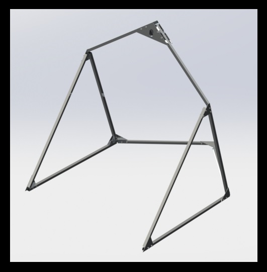
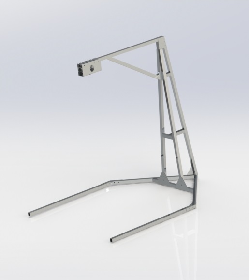
Standing Frame FEA
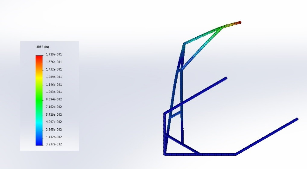 This analysis includes a basic FEA analysis in Solidworks. The main focus through the design and analysis process was limiting deflection at the top of the frame where the universal joint mounts, as the relatively low loads result in low stresses but not necessarily small deflections due to the frame's height. This process resulted in a maximum deflection of .17 inches and maximum stress of 8,374 psi at the universal joint mounting point, with loads being doubled for a factor of safety of 2.
Engineering analysis 3
Universal Joint Mount FEA
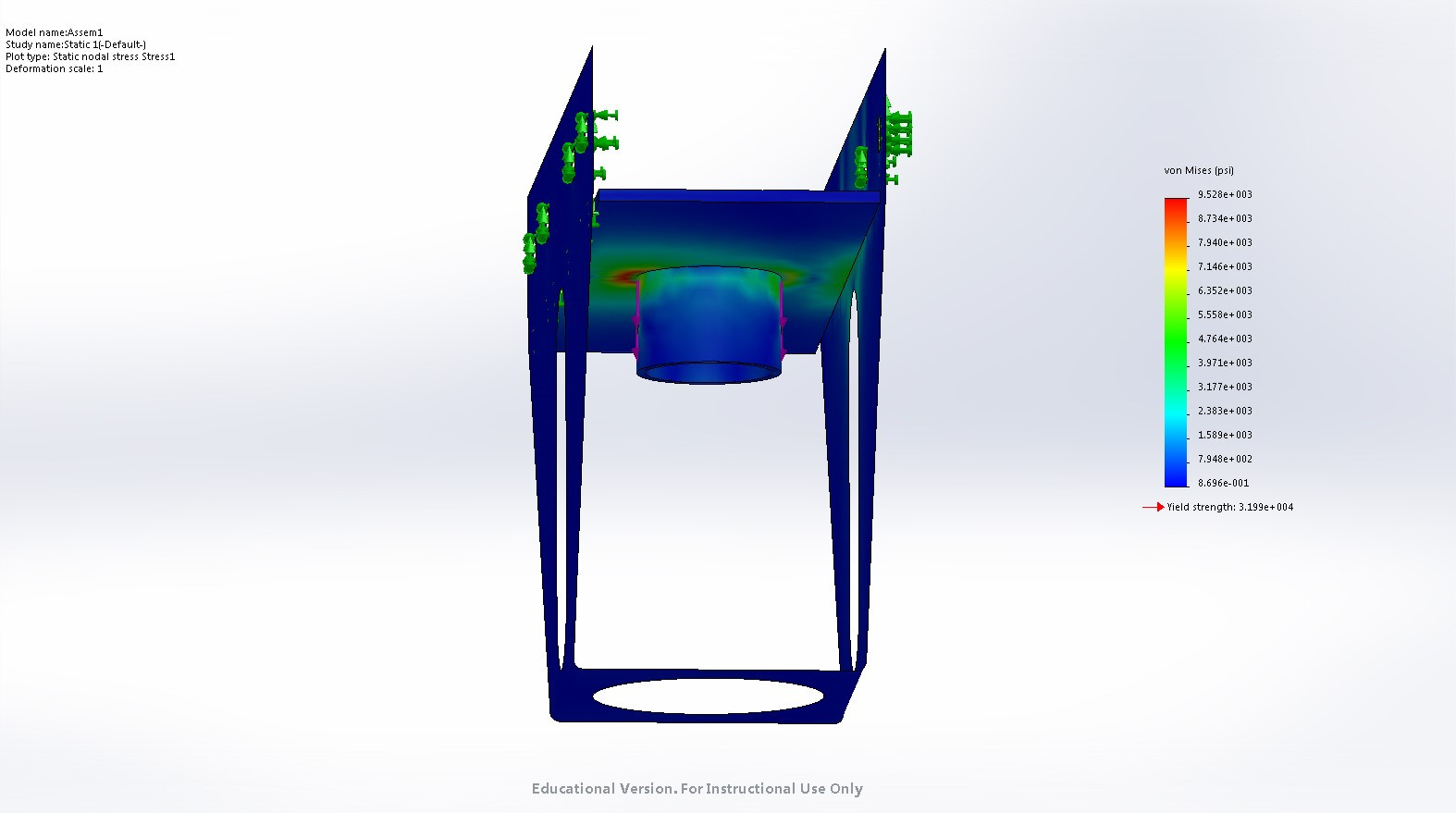
This analysis includes another FEA analysis on the universal joint mounting bracket. Again we can see the relatively low loads results in a very safe maximum stress of 4728 psi.
CAD Drawings

Swing Frame

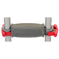
Swing with padding
Swing Parts

Leg Frame

Seat Frame

Back Frame
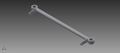
Slider Bar

Hanger Frame

Base Frame
Slide Lock(novameducalproducts.com)
Dimensioned Drawings:
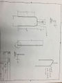
.jpg/90px-2016-05-05(2).jpg)
.jpg/67px-2016-05-05(3).jpg)
.jpg/67px-2016-05-05(4).jpg)
.jpg/67px-2016-05-05(5).jpg)
.jpg/120px-2016-05-05(6).jpg)
Frame Parts
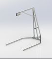
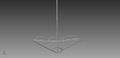
Standing Frame
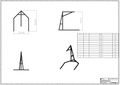
Dimensioned frame
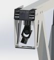
Universal Joint Mount attached
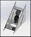
Universal Joint Mount
Universal Joint Mount
Bill of Materials
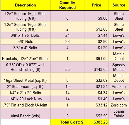 Nylon strapping : 10 ft : 6.90
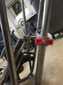
Side release buckle : 3 : 1.86
Total after restraint harness materials is 391.99
Nylon strapping : 10 ft : 6.90
Side release buckle : 3 : 1.86
Total after restraint harness materials is 391.99
Assembly Instructions
- Take inventory of all supplies
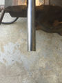
- Measure and cut tubing for each section of the seat and frame.
- Bend the two tubes for the base of the seat frame.
- cut out seat pans and all tabs (we used a plasma cutting table).
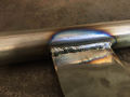
- Fish-mouth the tubing and weld tubing and seat sections.
- Measure and drill holes for different positions.
- Grind and sand all rough or sharp sections.
- Assemble the seat sections, attach to the frame, and bolt to the hanger bar.
- Prime and paint the metal frame.
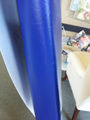
- Measure and cut the foam padding, fit the vinyl to pads, and Velcro the pieces to the metal pan.
- Secure all the sections, insert safety caps in end of tubing, and hang from the hanger frame.
Fabrication Process
.jpg/90px-2016-04-21(2).jpg)
.jpg/90px-2016-04-25(6).jpg)
.jpg/120px-2016-04-25(2).jpg)
.jpg/90px-2016-04-25(3).jpg)
.jpg/67px-2016-04-25(4).jpg)
.jpg/67px-2016-04-25(5).jpg)
.jpg/90px-2016-04-25(7).jpg)
.jpg/90px-2016-04-25(8).jpg)
.jpg/120px-2016-04-22(3).jpg)
.jpg/90px-2016-04-27(2).jpg)
.jpg/90px-2016-04-27(3).jpg)
.jpg/90px-2016-04-27(4).jpg)
.jpg/90px-2016-05-01(1).jpg)
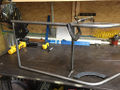
Testing and implementation
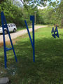
Describe testing, delivery, how used/received by the family After hanging the swing we added extra weight all the way to 200lbs and the frame withheld all loads with minimal displacement.
Photo of Completed design
Instructions for safe use
Provide a clear summary of safe use for the family. Do not use the device unless supervised by an adult that has been fully understood the safe use of this product. Do not attempt to change position while child is still in swing. Do not leave child unattended in swing. Make sure seat harness is tight and buckled securely. If you so not step in frame the swing can not hit you. Check connections to keep it continually safe. Contact professional if anything fails.
== Project Summary, Reflection ==