Sensor System
Contents |
Abstract
Adapt a tricycle to provide sensory feedback about surroundings for a vision impaired toddler.
Team members
- Ted Reed
- Alex McCoin
- Michael Rainey
- Brian Howard
- David Chesson
Mechatronics Design and Programming by:
- Josh Herwig
- Arturo Santa
Problem Statement/overview of the need
Major Cummings is a 2 yr. old boy with chronic calcium build up occurring on his optic nerve, causing partial sight failure that can last for multiple months. Major's vision alternates between good and legally blind. While he is legally blind, he cannot enjoy one of his favorite activities: riding his tricycle. Our goal is to provide a tricycle that will allow him to ride safely, regardless of the condition of his sight. To accomplish this, the tricycle must be equipped with a sensor system that warns the rider (Major) of an obstacle in his path. The design must also be safe; circuitry and components must be housed properly, and the rider and components must be safe in the event of a collision.
Design Specifications
1. Safe for use by toddler
2. Designed to help with Major's vision impairment
 a. Provide intuitive sensory feed back to inform Major of any obstacles or impending collisions
 b. On/off switch
 c. Sensory feedback easily distinguished from background
3. Easily operated and maintained by family
Conceptual Design
- We were originally told that he needed a entirely different style tricycle to help him. We later learned that he actually only needed the sensory help.
Design Concept 1
Our original design concepts included a set of rollers in which the resistance could be adjusted. A speaker and small generator would be rigged to allow music to be played while the rollers were in motion.
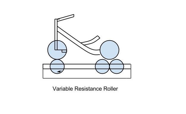
Although this system would allow Major the use of his tricycle while his vision is impaired, ultimately he would not gain any independence. We decided to abandon this design concept in favor of a system that would allow major to take his tricycle outside.
Design Concept 2
- The IR system was our first thought on how to detect obstacles.
IR systems
| Pros | Cons |
|---|---|
| Inexpensive | Sunlight issues |
| Easy to work with | Signal Decay |
| Narrow Beam Width | |
| Different reactions for surfaces |
Design Concept 3
- Ultrasonic sensor would also be a valid choice.
Ultrasonic sensor
| Pros | Cons |
|---|---|
| Can work outside | Thrown off by sound absorbing objects |
| Very Accurate | Expensive |
| Multiple options for signal | Micro-controller needed |
Evaluate concepts/select candidate
The first design would work if we were still running with our original goals. Although the goals have changed, the second two designs are the only choices to go forward with in this design. Both sensor systems have their benefits. IR sensors for the simplicity of working with and price cost. On the other hand, IR sensors do have problems with sunlight and a narrow beam width. Ultrasonic sensors are very accurate and work well outside. They are more expensive than the IR sensors and we would need a micro-controller. After going over all the details we have chosen to go with ultrasonic sensors because they have the ability to work outside and less chance of an error with distance detection.
Detailed Design
This section will describe a detailed design process
Description of selected design
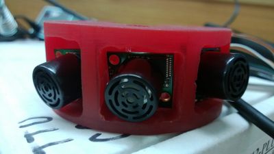
With the help of the Mechatronics group, We have decided to go with three sensors along the handle bars and place all the electrical components under the seat, along with the batteries.
Detailed description of selected design
- Sensor placement
 There will be three sensors placed on the handle bars. All three will be pointed at a different angle that allows
 the beams to spread with as little interference as possible.
- Wiring
 We will be running the wires through the pipes of the tricycle. This will hide them from sight and protect them from
 getting damaged.
- Motors
 Motors will be placed in each handle bar to alert the child. This is for when there is an obstacle on the right side
 it will run the one in the right handle bar to signal to turn left.
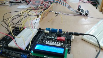
- Micro-controller
 The micro-controller will be placed under the seat in a protective cover. It will be programmed to read the sensors.
 When it reads and obstacle it will send power to the motor in the handle in the respected side to alert the child.
Engineering analysis 1
One of the first aspects we had to take into consideration after deciding on a design was the orientation and number of sensors to use. Some considerations were:
- Cross interference between ultrasonic sensors
- Enough sensors to accommodate tactical and sensory feedback.
- Bandwidth
- Dead zones between sensors
After considering our options we came up with four unique solutions:
.jpg)
| One US Sensor | Two US Sensors | One US One IR | Three US Sensors | |
|---|---|---|---|---|
| Pro's | No interference issues | Increased range | Increased range, Blind spots accounted for | Dramatically increased range |
| Cons | Very limited range | Interference issues | Separate programming for sensor types | Must overcome two interference issues |
Engineering analysis 2
As a result of the previous analysis, the Three US sensor setup was chosen. To combat the interference, the three sensors were placed on different frequencies.
Another positive effect of this setup (other than ones already mentioned) was the ability to included directional sensory feedback via micro-controller coding coupled with vibrating disk motors in the handle bars.
If the three beams of the US sensors are split into multiple "zones", each corresponding to a different motor-driven tactile output, then the rider could learn to discern roughly where the object is relative to his path.
After some experimenting, it was decided by our partnering Mechatronics team to split the beams into five zones. The zones are as follows:
- Far left
- Interface between left sensor and middle sensor
- Middle-most portion of the collective US beams
- Interface between middle sensor and right sensor
- Far right
For example, if something was approaching the rider on the far right of his bath, his right handle would vibrate to provide a tactile feedback communicating the location of the obstacle. If the object were only slightly to the left of the rider's path, it would correspond not to Zone 1, but to Zone 2, which would vibrate the left handle strongly, and the right handle lightly. In this way, the rider can learn to distinguish the general location of an obstacle, even when visually impaired.
Engineering analysis 3
Because this bike should be taken both outside and inside, another concern was adjusting the programming in such a way that fit both environments. After many meetings, our group decided that the main code adaptations would have to be made for inside, not out. The hallways and increased number of obstacles proved to be difficult to code around.
Consider this: the three-sensor-equipped bike is going down a hallway in the house. The sensors would read the constant wall as a very, very long obstacle and provide a constant, useless feedback that would drown out any feedback about anything actual obstacle in the path of the bike. For this, we considered completely revamping the code to ignore constant feedback, or possibly even limiting the distance reading to a certain window that wouldn't allow the bike to reach the wall, but would still read any imminent obstacles.
After analyzing the pros and cons of these two ideas, we decide to add an extra button to the power control that would toggle between two modes; one mode for inside would ignore any readings over 50cm, while the other would respond to any readings within a few meters of the bike. This way, the rider could essential go from one environment to the other with a simple press of a button.
CAD Drawings
Insert drawings of all parts and the assembly
Bill of Materials
- Microdragon $55-65
- RC Battery $30-50
- Vibrating mini motor discs $1/ea
- Sensors x3 $45
- Buzzers x2
- wiring
- sodder
- epoxy x2 $9.00
- housing
Assembly Instructions
No assembly required.
Fabrication Process
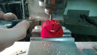
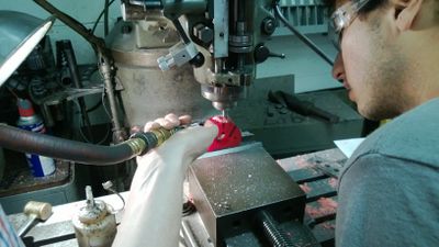
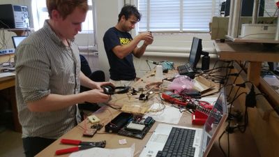
.
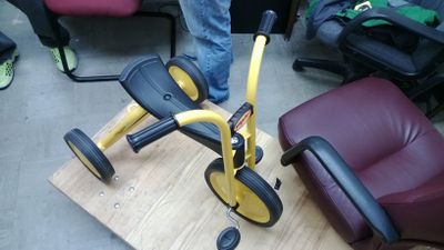
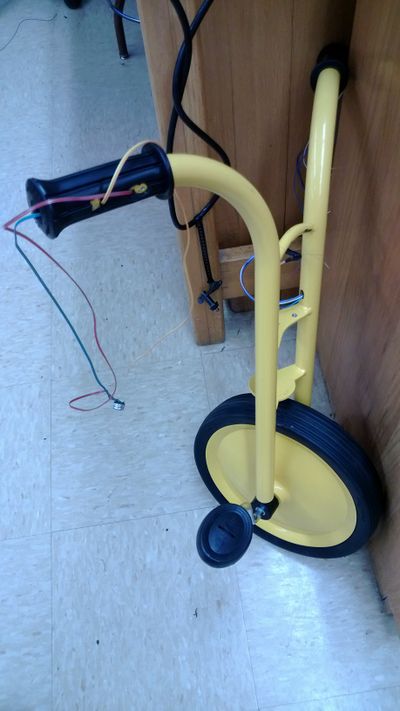
Completed design
Insert pictures of the final product
Instructions for safe use
- Keep away from water.
- No Sudden drops.
- Do not open the casing under the seat without proper supervision.
- Adult super vision of young children required.
- Never allow more than one rider.
- Do not operate on steps, steep slopes, roadways, or swimming pool areas.
- Protective equipment and shoes required for riding.
For Battery:
- Charging and discharging batteries has the possibility for explosion, fire, serious injury to persons, and damage to property.
- If battery shows signs of fatigue and/or damage, immediately discard in appropriate manner.