Sensory Swing
Abstract
Our client was a family with a young boy who has social anxiety and sensory concerns. The goal of our project was to design and build a "comfort area" for the child consisting primarily of a cocoon-like sensory swing suspended from a portable frame. Soothing sounds (water, guitar music, etc.), soft textiles, and a tent-like canopy over the swing were to be incorporated into the design for added comforting effects. For the swing itself, we found a variety of options which can be readily purchased online. The primary challenges of the project were 1) to design a support frame that would be safe and sturdy yet portable, and 2) to design a tent-like fabric cover that would not be overly constraining to the swing's motion. After developing and evaluating five design concepts, we chose one consisting of a four-legged support frame which can fold to fit through doorways when needed. A night light projector/sound machine would mount near the top of the frame, providing soothing sounds and lighting inside the covered area. We performed a few analyses on our design involving forces, stress, deflection, size, and weight. Having obtained satisfactory results, we believe our design is safe and practical, but further testing after fabrication would be necessary to verify this. Unfortunately, we were unable to fabricate our design due to the COVID-19 pandemic and resulting lockdown. However, we are grateful for all we learned about the engineering design process. The project will likely get passed to another team next fall, and we would be glad to play a part in mentoring the next team that is to carry this project forward.
Team members

Left to Right - Jonathan Kelley, Matthew Baldwin, Henry Pace, and Oussama Amara
Problem Statement/overview of the need
Our client is a family with a nearly two-year-old boy who has sensory issues and easily becomes anxious in social situations. The child's parents and therapist would like our group to build a sensory swing or related object that would provide him with a physical area to retreat when he feels overwhelmed. Soothing sounds (water, guitar music, etc.), soft textiles, and a tent-like canopy over the swing would provide additional calming for the child. The swing needs to hang from a portable frame that can be moved from room to room.
Design Specifications
Requirements
- Swing plus frame must be able to be moved from room to room with relative ease. This would require either the length or width of the base to be under 2'-9" or for the design to be easily collapsible in order to pass through doorways.
- Must be able to support the weight of the child for several years to come. The goal we have set (with the approval of the family) is for it to last until child is 10 years old. This means the structure would have to hold about 100 lbf static weight plus additional force due to child swinging or jumping into the device. Stress analysis will have to be performed in CAD and/or on paper to ensure this requirement will be met with an appropriate factors of safety applied.
- Must be stable such that their is no risk of the frame falling over when child swings.
- Cannot have any hard/sharp edges or tripping hazards, as these could pose a risk to the child's safety.
- Should incorporate a tent-like cover around the frame so that the child can feel safe and secluded. This cover must have the ability to be opened and closed on at least one side by the child's parents as needed.
- Design should incorporate an appeasing fabric texture, preferably felt or something very soft, inside the swing.
- Design should be equipped with a sound machine that will give the child the ability to play calming sounds inside the swing frame enclosure when he chooses. He likes water noises, so a sound machine equipped with several types of these sounds would be preferred. The family would also like to have the ability to play sounds through the machine via Bluetooth connectivity to their phones.
- Design should incorporate some sort of soothing lighting inside the swing frame enclosure which can be turned on and off at the child's or parents' choosing.
Preferences
- Ability of the tent-like cover to be "rolled up" or otherwise adjusted for varying degrees of seclusion.
- The child particularly likes stars, cats, Mickey Mouse, and the color purple. Incorporating some of these "favorite things" of the child into our design would be a nice addition.
Background research
Children with autism struggle with sensory inputs because their vestibular system is underdeveloped. The vestibular system governs our sense of movement and balance and is located in the inner ear (1). According to a blog post at NeuroScientificallyChallenged.com, "the vestibular system is essential for normal movement and equilibrium." (2) The lack of a fully-developed vestibular system in children with autism can cause them to be easily overwhelmed by sensory inputs. A sensory swing helps by stimulating the vestibular fluids in the ear. This, in turn, helps the child get used to the sensation of moving, giving him/her more confidence navigating his/her environment. Additionally, the cocoon-like, cuddling nature of the swing provides a calming effect for the child.
1. What Exists Already; Similar Products
- A fair amount of swing concepts and frames are available on the market. Here are photos of a few we've found.
-
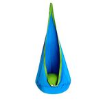 OUTREE Kids Pod Swing Set (3)
-
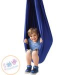 Raindrop Swing (4)
 -
 Cotton Rope Hammock Swing Chair (5)
 -
 Sorbus Hanging Rope Hammock Chair Swing Seat (6)
 -
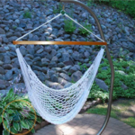
 Ashburnham Hammock Stand (7)
 -
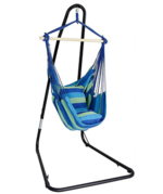
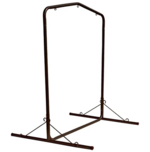 Pawley's Island Steel Swing Stand (8)
2. Availability of Materials and Products
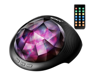
- Most of the fabric pieces required such as the swing itself are readily available online. The swings we found came in a variety of both larger and smaller enclosure areas. Some had bean bags in the bottom which provided a larger enclosure, whereas others did not have the additional support. There are many different "noise machines" online that would fulfill the requirement of having calming background water noises. For the lighting, Christmas lights could easily provide a soft soothing light inside the covered area surrounding the swing. We also found a "projector light" online that would provide both soothing sounds and lighting. See photo below.
3. Gaps in Existing Products or Technology to be Addressed
- All of the noise makers we have looked at thus far with Bluetooth ability have not been designed for children, so our team will have to modify the buttons on the device in order to make it more child-friendly. In addition to this, all of the frames we have looked at are made for outdoor use, and are far too large to fit through a standard doorway. Because of this, We will have to make our own from scratch.
References:
- Katzman S. "Why Children with Autism Love Sensory Swings." InYardProducts.com. Swings. N/A. Accessed February 25, 2020.
- Dingman M. "Know Your Brain: Vestibular System." Neuroscientifically Challenged. Know YourB Brain. Published November 15, 2015. Accessed February 25, 2020.
- N/A. "OUTREE Kids Pod Swing Seat 100% Cotton Child Hammock Chair for Indoor and Outdoor use (Blue)." Amazon.com. Amazon. N/A. Accessed March 24, 2020.
- N/A. "Raindrop Swing." Fun and Function. Fun and Function. N/A. Accessed March 24, 2020.
- N/A. "Cotton Rope Hammock Swing Chair With Spreader Bar." Fun and Function. Hammock Swing Chair. N/A. Accessed March 24, 2020.
- N/A. "Sorbus Hanging Rope Hammock Chair Swing Seat with Adjustable Multi-Use Stand for Any Indoor or Outdoor Spaces." Amazon.com. Amazon. N/A. Accessed March 24, 2020.
- N/A. "Ashburnham Hanging Metal Hammock Stand." AllModern.com. Hanging Metal Hammock Stand. N/A. Accessed March 24, 2020.
- N/A. "Pawley's Island SWSLBK Steel Swing Stand, Black." Amazon.com. Amazon. N/A. Accessed March 24, 2020.
- N/A. "SOAIY Aurora Night Light Projector and Sleeping Soothing White Noise Sound Machine." Amazon. N/A. Accessed March 24, 2020.
Conceptual Design
Design Concept 1
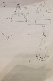
One of our initial ideas was to create a tent similar to a tee-pee that supports a swing in the center. This design includes a way to fold structure in order to move it to other rooms, and it allows movement of the swing in all directions. Also incorporated is a chain to adjust the sitting height of the swing to accommodate the child's growth. A fabric cover would be fitted around the tee-pee with an opening in the front.
Pros:
Adaptable
Aesthetic
Portable
Lightweight
Easy to assemble
Cons:
Very tall
Limited space inside
Possible stability concerns
Design Concept 2
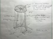
This is a single-arm support concept similar to the single-arm support shown in the Background Research section. With this design, a wheel would be mounted on the top, and the curtain would slide along the rail like a shower curtain. Potential benefits of this design include reduced size and weight, ease of fitting through doorways, and ability of the child to have a lot of swinging space in all directions. Some downsides include a possible lack of stability compared to other designs and limited space inside when the curtain is closed.
Pros:
Easy to assemble
Comfortable and sturdy
Easy to move around the house
Cons:
Limited space inside
Smaller base, so more likely to tip over
Possible trip hazard with the U-shaped support at the bottom; may need modification
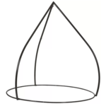
Design Concept 3
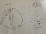
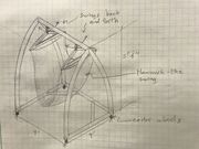
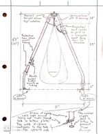
This design concept has a tent-like shape, with supporting legs that make an arc and connect at the top. Note that currently this design would not fit through doorways, so it would have to be adjusted to allow folding of the frame. A fabric cover would be applied around the sides of the frame with an opening in the front end to allow access. The swing would hang from the top connector, and the projector light/sound machine would be hung near the top. For the projector light, one possible configuration would be to point the light upward and have a reflecting surface that directs the light in many directions, providing a neat effect (depicted in photo). Though not shown in the photo, caster wheels could be added to the base.
Pros:
Aesthetic
Sturdy, wide base prevents tip-over
Swing can move in all directions
Cons:
Difficult to manufacture (particularly the curved legs)
Difficult to collapse
Current configuration does not fit through doorways but could be modified to fold inward
Potential trip hazard with the horizontal support across the front; would need modification
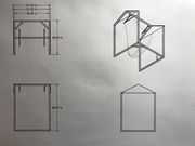
Design Concept 4
This design is a somewhat simpler concept. Square rather than round tubing would compose the frame. As opposed to all the vertical supports meeting at the top, a beam supporting the swing would run across the top. A fabric cover would be fitted around the frame with an opening in the front. Also, instead of a teardrop-style swing, a hammock-style swing would be used. This could provide the benefit of being easier for the child to climb in and out of. Like Design 3, this design would need adjustment in order to fit through doorways. The light/sound machine could be mounted on one of the side walls near the top, projecting light at a slight angle downward. Though not shown in the photo, caster wheels could be added to the base.
Pros:
Easy to manufacture
Sturdy and stable
Hammock-style swing would allow easy access by the child and would give child more space
Cons:
Unable to fit through doors; a dimension would have to be shortened, or the design would need to be able to fold
Swinging motion limited to one direction
Not as aesthetically pleasing as the others
Bars separating the sides of the hammock swing may hit the fabric cover when swinging; may need adjustment
Design Concept 5
This design is very similar to Design 4, only the straight side walls have been replaced with curved supports to improve aesthetics. Like Design 4, this design would incorporate the hammock swing concept, and it would need adjustment to permit movement through doorways.
Pros:
Aesthetic
Sturdy, stable
Hammock-style swing gives child easy access and more space
Cons:
Unable to fit through doors; a dimension would have to be shortened, or the design would need to be able to fold
Swinging motion limited to one direction
More difficult to manufacture than the other hammock-style design
Evaluate concepts/select candidate
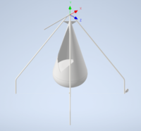
For our design evaluation matrix, we examined eight criteria, with the safety and portability categories given higher weight. Before filling out the matrix, we met a second time with the child's family and therapist to discuss the designs we had come up with. They preferred the teardrop-style swing over the hammock swing since it would allow the child to swing in all directions. Although designs 4 and 5 could potentially accommodate the teardrop swing, the other designs were more conducive to this. Comparing design 3 with designs 1 and 2, we believed design 3 offered greater stability and could be modified to accommodate movement through doorways. All things considered, we landed on design 3 (with a few modifications discussed in the next section).
![]()
Detailed Design
Description of selected design
After discussing and reviewing our criteria for the swing, we chose a modified version of our third design concept. We believe this design is superior in terms of stability and overall safety. The primary modifications to be applied are as follows:
- replacing the rigid connection at the top with one that will allow the frame to be folded to fit through doorways
- replacing the horizontal tubes with thin cable X-braces (significantly reduces trip hazard, lowers cost)
- bending the support legs at a single location rather than attempting to make the tubes follow a continuous arc (greatly improves ease of manufacture)
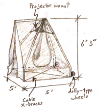
- increasing the size to cover a 5 ft x 5 ft footprint and reach a height closer to 6 feet
- replacing caster wheels with dolly-type wheels mounted on two support legs
- adding a pole across the top to hold up the fabric at the entrance
Detailed description of selected design
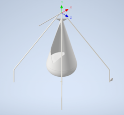
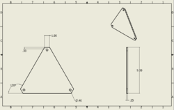
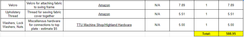
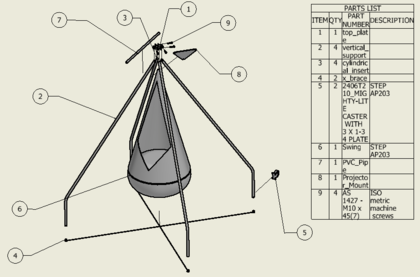
Our selected design is a tent-like frame that is five feet wide, five feet long, and 6 feet - 3 inches tall. It will be supported by four legs, each made out of DOM 2020 steel tubing. The legs will be pinned to a top plate in a way that allows the frame to be folded into a more compact size in order to move through doorways. The legs will also be connected towards the bottom with a cable X-brace to prevent the legs from spreading apart too far. Note that a cord cover will be placed over the X-braces to prevent a trip hazard. The swing will hang from the top plate in the middle, and a tent-like cover will be fitted with Velcro around the frame to create a hide-away for the child. Rather than caster wheels, dolly-type wheels will be mounted on two of the support legs. This will improve the sturdiness of the structure when sitting on the ground while allowing it to be rolled when tipped up slightly. Mickey Mouse-patterned fabric will be sewn onto the inside of the swing to provide an additional fun, sensory effect for the child.
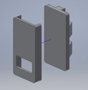
Inside, we will mount a projector light/sound machine towards the top to create various soothing effects. This will be accomplished by gluing the sound machine to a triangular-shaped, 3D-printed mount which will hang from the frame via thin cables. The mount can be detached in order for the sound machine to be recharged periodically. There will be a custom 3D-printed holder for the remote that controls the lights and sounds, which we will mount on the frame towards the bottom so that the child has control over the sounds. The opening in the remote control holder will only permit the child to access the buttons changing which sound is played (see photo below). This is per the family's request, as they would like to prevent him from being able to access the volume control, light adjustment, etc. We designed the holder such that it will (hopefully) be difficult for the child to remove the remote from the holder while he is very young. A small hole in the bottom of the holder will allow the child's parents to push the remote out from the bottom so they can adjust the settings of the sound machine when needed.
-
 Swing Frame Assembly
 -
 Swing Overview
 -
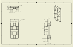
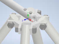 Top Plate Connection
 -
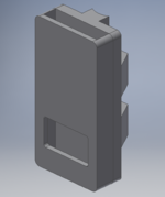 Remote Control Holder
 -
 Overall Layout
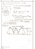
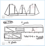
Details of the fabric layout are shown in the photos below. The photo on the right depicts how the fabric sections can be cut from the supply roll.
-
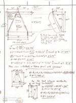 Fabric calculations - page 1
 -
 Fabric calculations - page 2
 -
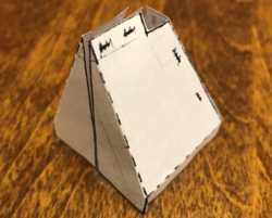 Paper model of fabric
 -
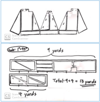 Fabric sections and layout

Analysis
The most important factor that we considered while discussing analysis for this project is safety. The three types of analysis that we chose include the following:
- Hand Calculations - First we performed a few hand calculations on our frame so that we had a reference when we ran our stress analysis in Inventor.
- CAD Stress Analysis - Second, we used finite element stress analysis capabilities of Inventor to determine the maximum stress, maximum displacement, and minimum safety factor of the assembly when subjected to a 200-pound load (load choice explained below).
- Size and Weight - Finally, we calculated the overall weight and size of the assembled swing, making sure the swing could fit between doorways when folded.
Before discussing each calculation, a brief discussion of the static force used in the calculations is needed. Although we only need the swing to support the weight of a boy weighing 100 pounds (max), we anticipate the child will bounce up and down on the swing a bit. This will introduce impact stress into the system. Modeling impact stress, however, can be quite complicated. To account for some impact forces, we decided to double the static weight force used in our calculations and aim for a safety factor in the range 3-5 on top of that. Fatigue may also be a consideration given that the swing will be unloaded and loaded as the child gets in and out. A fatigue stress calculation is given at the end of Engineering Analysis 2.
Also, note that since the fabric cover will prevent the swing from swinging outside the area enclosed by the frame, we did not believe it necessary to perform a tip-over stability analysis given the large 5-ft x 5-ft footprint of the frame. If the fabric were to be removed, allowing the swing to go beyond the frame area, a stability analysis involving the location of the child's center of mass at the outermost swinging point may be worth considering. Keep in mind that this swing is not intended for high swinging.
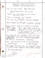
Engineering Analysis 1 - Hand Calculations
All hand calculations assume the load is evenly distributed across all four legs, thus each leg holds 50 pounds.
The first calculation (left photo) estimates the maximum bending stress experienced in one of the support legs. The supports are modeled as a pin connection at the bottom and a sliding connection at the top. The outer radius is 0.5", and the inner radius is 0.435" (used in moment of inertia calculation).
The second calculation (middle two photos) estimates the maximum shear stress in each of the pins connecting the poles at the top.
The third calculation (two photos on right) estimates the tension in each of the X-braces. The results from this calculation yielded a cable stress of a little less than 30 lbs. The 3/32" cable we selected is rated for a 184-lbf safe working load -- well over the tension expected in the cable.
-
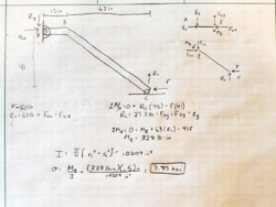 Support leg - max bending stress calculation
 -
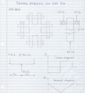 Pin shear stress calculation - page 1
 -
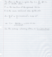 Pin shear stress calculation - page 2
 -
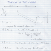 Cable tension calculation - page 1
 -
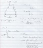 Cable tension calculation - page 2
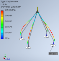
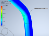
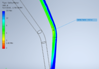
Engineering Analysis 2 - Finite Element Analysis
We then used Autodesk Inventor's finite element analysis (FEA) tool to determine the maximum stress, maximum deflection, and minimum safety factor for the whole assembly under a static load of 200 lbf. Because the base of the swing will be supported by rubber stoppers, we were unsure if the stoppers would behave most like a rigid support, a sliding contact, or a pin connection. Thus, we analyzed all three scenarios in Inventor and compared results. The maximum stress resulting from each case was similar (although the location of max stress differed as expected).
Below: Stress analysis modeling base as a rigid support
-
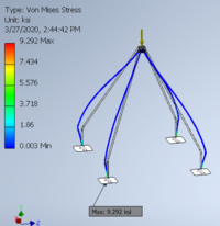 Fixed Support - Von Mises Stress
 -
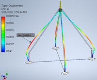
 Fixed Support - Displacement
 -
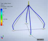
 Fixed Support - Factor of Safety
Below: Stress analysis modeling base as a sliding support (cables prevent legs from moving outward)
-
 Sliding Support - Von Mises Stress
 -
 Sliding Support - Displacement
 -
 Sliding Support - Factor of Safety
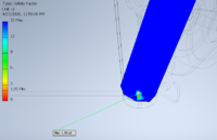
Below: Stress analysis modeling base as a pinned supports (assuming high friction between rubber stoppers and floor, this is most accurate simulation)
-
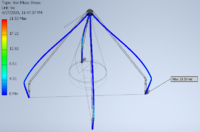 Pinned Support - Von Mises Stress
 -
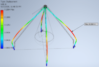 Pinned Support - Displacement
 -
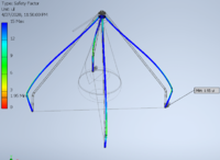 Pinned Support - Factor of Safety
 -
 Pinned Support - Factor of Safety (exploded view)
 -
 Pinned Support - True Max Stress (exploded view)
 -
 Pinned Support - True Min. Factor of Safety (exploded view)
Note: The low factor of safety and high von mises stresses in the above pinned support analysis occur at a hole in the supports that won't actually exist. This hole creates a stress concentration, and they have been placed in the CAD drawing for the sole purpose of adding the "pinned" constraints to the assembly. The true maximum stress and minimum factor of safety are shown in the exploded views and labeled "True Max Stress" and "True Min Factor of Safety" respectively.
Comparing our hand calculations with the three FEA analyses, the maximum stress calculated was around 10.5 kpsi (FEA analysis - pinned support). The factor of safety calculated in Inventor is based on a yield strength of 42 kpsi (the default value for DOM 1018 Q&T steel in the Autodesk materials library). This is a conservative value for the yield strength. Based on this value, the minimum factor of safety for yielding was calculated as n=(Yield Strength)/(Max Von Mises Stress)=(42 kpsi)/(10.5 kpsi)=4.0. This is within our goal of 3<n<5. The maximum deflection calculated by FEA analysis also seems to be within reasonable bounds.
Considering that this swing will be loaded and unloaded often as the child gets in and out of the swing, a quick fatigue calculation was performed to estimate the factor of safety if the swing is to last for infinite (more than 10^6) cycles. For this calculation, equations and AISI 1020 steel data were taken from Shigley's Mechanical Engineering Design textbook (10th edition). See hand calculation and textbook reference below. Using the modified Goodman criteria for fluctuating stress, the minimum factor of safety was found to be n=3.37. (Keep in mind that tensile strength values vary somewhat depending on the source used.)
Reference:
Budynas, Richard Gordon, and J. Keith Nisbett. Shigley's Mechanical Engineering Design. 10th ed., Mcgraw-Hill Education, 2015, pp. 290-302, 313-314, 1048.
-
 Fatigue Factor of Safety - Page 1
 -
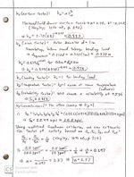 Fatigue Factor of Safety - Page 2
Engineering analysis 3
For our third analysis, we wanted to estimate the size of the folded swing and the weight of the frame (not including the sensory swing itself, which can easily be detached for transporting). The results rendered a folded swing size that can easily fit through a 2.5ft-wide doorway and a weight that lends well to easy transportation.
Size:
Unfolded - 5’ x 5’ x 6’3”
Folded - 1.5’ x 1.5’ x 7’
-
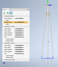 Folded Swing Frame width
 -
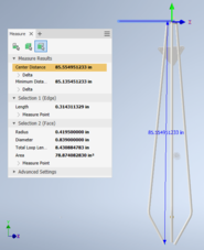 Folded Swing Frame Height
Weight:
B = Bars (7 Feet Long Steel)
TP = Top Plate (6061 Aluminum)
M = Misc. (Wheels, fabric, swing)
W = Weight = 4*B+TP+M
B = Weight/foot*Length of bar = .65lb/ft*7feet = 4.55lbs
TP = Volume*Density
= 4.4 in^3 * .0975 lb/in^3 = .42lb
M = approx. 10 lb
W = 4*4.55lbs+0.42lbs+10lbs = 29 lbs
W = 29 lbs
CAD Drawings
Note: All dimensions in English units (inches). Refer to assembly instructions and drawings for correlations to part numbers.
-
 Swing Frame Assembly
 -
 Part 1 - Top piece
 -
 Part 2 - Legs
 -
 Part 3 - Cylindrical inserts
 -
 Part 4 - Cable fastener
 -
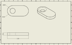
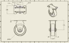 Part 5 - Wheels (McMaster-Carr)
 -
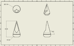 Part 6 - Swing body
 -
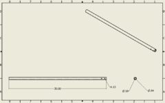 Part 7 - PVC pipe
 -
 Part 8 - Projector mount
 -
 Part 10a - Remote control holder - bottom piece
 -
 Part 10b - Remote control holder - top piece
Bill of Materials
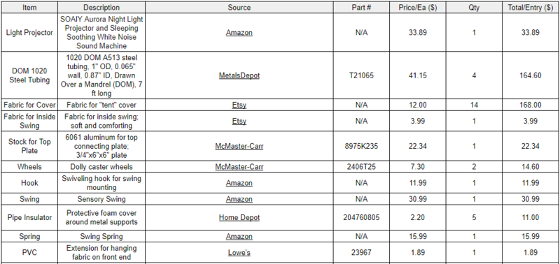
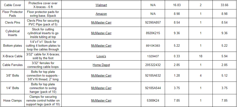
Total Cost: $588.95 (does NOT include tax and shipping)
Clickable Links:
- Light Projector
- DOM 1020 Steel Tubing
- Fabric for Cover
- Fabric for Inside Swing
- Top Plate
- Wheels
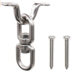
- Hook
- Swing
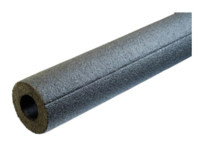
- Pipe Insulator
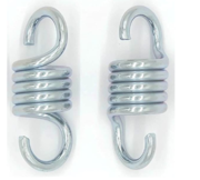
- Spring
- PVC
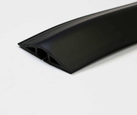
- Cable Cover
- Floor Protector Pads
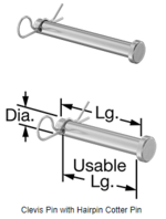
- Clevis Pins
- Cylindrical Inserts - Stock
- Bottom Plates - Stock
- Cable for X-braces
- Cable Ferrules
- 3/8" Bolts
- 1/4" Bolts
- Hose Clamps
- Velcro
- Upholstery Thread
Assembly Instructions
-
 Full View of Exploded Assembly
 -
 View of Top Exploded Assembly
 - Overall Layout
-
 Fabric sections and layout
Below are the exploded assemblies of the swing frame. On the left is a full view of the swing with part numbers listed for reference. Middle-left is a zoomed in view, so one can more easily see how the top plate, bolts, and cylindrical inserts fit together. Middle-right is a sketch of the overall layout as viewed from the side. On the far right is a depiction of how the fabric pieces for the cover can be cut from the fabric stock and stitched together.
Note*
Several objects (denoted by * below) were not represented in the CAD assembly drawing because 1) they do not constitute the critical structural aspects of the design or 2) they will be purchased online rather than manufactured by our team.
To assemble the swing, one will start with the legs (2). Pipe insulator (15)* will be slid onto the tubing with portions cut out to allow for attachment of various components. Cable fasteners (4) will be welded onto the base of the legs. This piece will allow us to thread the cable through while keeping the cable close to the ground to avoid trip hazards. Rubber pads will be adhered to the bottom of part 4 to protect the floor (see Overall Layout photo above). Wheels (5) will be welded onto the backs of legs 2 and 3 (numbered counterclockwise from the right of the entrance). Cylindrical inserts (3) will be inserted into the tops of the legs and welded into place such that the holes align with those in the legs. Next, the legs will be attached to the top piece (1) using bolts (9) that thread through the two aligned holes. The legs should then be fastened together at the bottom using the cables. A Hook (11)* will be bolted to the underside of part 1 (allows full, 360-degree rotation of the swing). A spring (12)* will then connect the hook to the swing body (6). The PVC pipe (7) will then be attached to the upper side of part 1 using clevis and cotter pins (13)*. The projector/sound machine (14)* will be secured to the 3D-printed projector mount (8) via adhesive. One will then use string or cable to tie the three holes in the projector mount to legs 2,3, and 4. This will support the projector, holding it at an angle downward so the light projects into the tent structure. The fabric cover (17)* will then be attached to the frame using Velcro sewn onto the fabric. Soft, Mickey Mouse-patterned fabric will be sewn onto the inside of the sensory swing. Finally, a cord cover (16)* will be placed over the cables to minimize trip hazards.


Fabrication Process
Unfortunately, we were unable to move forward with the fabrication stage of the project due to the 2020 COVID-19 pandemic. The project will likely be passed to another team, hopefully in the fall of 2021. Please see the Recommendations for Moving Forward section at the bottom of the page.
Testing and implementation
Describe testing, delivery, how used/received by the family
Photos of Completed design
Insert pictures of the final product
Instructions for safe use
Do not use this device unless supervised by an adult that fully understands the safe use of this product.
- Not for adult use! Maximum weight capacity of 100 lbs.
- Do not use the swing while in its folded state.
- After unfolding swing, place cord covers over cable X-braces to prevent trip hazards.
- Do not climb on the outside of the fabric cover and frame.
- Do not rough-house inside the swing.
- Other safety instructions determined upon testing after fabrication.
Project Summary, Reflection
Through the course of this project, we learned a lot about the engineering design process. We learned how to be creative, exploring a wide range of design possibilities in order to land on a final design that would, according to our best estimation, meet our client's needs most effectively. A significant challenge we encountered was how to make the swing frame roomy and sturdy while still being able to fit through doorways. Performing stress analysis in Inventor allowed us to see what areas of the structure needed tweaking in order to maintain structural integrity. Once we had a frame design we were satisfied with, there were technical issues to deal with such as how to attach the cable X-braces, how to design the fabric cover, and how to attach the projector/sound machine to the structure. Slowly but surely, we worked out these details through team collaboration. Although we were unable to fabricate the swing due to the COVID-19 pandemic and resulting lockdown, we believe our final design is practical, safe, and manufacturable. Note that if the design were to be fabricated, testing should be performed in order to verify the safety of the swing before sending it to the family. We are grateful for all this project taught us about engineering design and analysis.
Recommendations for Moving Forward
Moving forward, we recommend that the team picking up this project take some time to look over our design and background research. Doing so will help the next team to understand some of the issues we encountered so as to get a better idea of the challenges involved. We recognize that our design is not necessarily the only workable concept. We encourage the next team, working alongside the child's family and therapist, to critique this design in order to identify areas for improvement. Possible improvements to the analysis process include a more detailed investigation into impact forces and a stability analysis (see introductory paragraphs of the Analysis section). Another potential improvement would be to incorporate more of the child's "favorite things" into the design (see Design Preferences in the Design Specifications section). We recommend that the next team seriously ponder other ideas which we may not have thought of, arriving at a design that is well-suited to the client's needs.
If future groups have any questions regarding design or manufacture of this project, please reach out. We are all very disappointed that we were not able to see this project through as we were very involved and want to see it succeed. :)
Henry Pace: (931) 539-5126, hrpace42@gmail.com
Oussama Amara: samuamara@gmail.com
Matthew Baldwin: (931) 703-3595
Jonathan Kelley: (931) 623-4111, jpkelley77@gmail.com