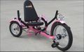
Tricycle for children with visual impairment
Abstract
The goal of this project is to design a system to go on a tricycle that will aide a child with visual impairment in navigation. This system will need to detect objects and give the child some type of sensory feedback.
Team members
- Photo of team

Justin Jones, Garrett Wallace, Jonathan Stephenson, Lucas Simmons, and Nick Bales Acknowledge help of others
- Dr. Canfield
Problem Statement/overview of the need
To design a system for a tricycle to aide a child with visual impairment with navigation. The problem has three main areas of focus:
    1. What sensors should be used?
    2. How can mapping be achieved with these sensors?
    3. How can this information be relayed to the child in a meaningful way?
Design Specifications
- Be able to detect objects in approximately an 8ft semi-circle.
- Be able to give location within +/- 6 inches.
- Sensor should have ability to communicate with onboard electronic system.
- The output should intuitive for the user. (i.e. Shouldn't take a lot of learning to understand the output.)
- The unit should be able to be contained on a tricycle.
Background research
There are very few similar systems that exist. The group was able to identify two similar systems. One was a research project by another university and the other is a system on the European market. As such, this system has very little availability. These two systems are also designed more towards adults or older children. Ultrasonic sensors were used in both of these systems. When discussing possible improvements, the team that did the research project discussed the use of higher quality sensors. They also thought that their feedback system, which used a system of beeps, could be improved.
University of New Hampshire Research Project:
Ultra Bike-European System for Bicycles:
https://www.ultracane.com/ultra_bike
Conceptual Design
During our conceptual design process, our main focus will be on what type of sensors to use. We will look at ultrasonic sensors, infrared sensors, and Lidar sensors.
After the choice of a sensor type, detail design will focus on how to implement the sensor(s) and how to map with it.
Design Concept 1-Ultrasonic Sensor
This type of sensor uses sound waves to detect objects. Sound waves are emitted and the time that it takes for reflected waves to return is used to determine how far away an object is. This design would use an array of multiple ultrasonic sensors to cover the 180 degrees in front of the tricycle. A previous design team used ultrasonic sensors in a three-sensor array.
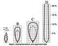
- Ultrasonic sensors generally emit sound waves in a wide cone. Sensors can be selected that create a cone between about 15 degrees to above 45 degrees.
- A sensor that emits a wide cone would be helpful in covering a larger area with fewer sensors.
- However, a wider cone will also lead to reduced accuracy.
The problem with using a sensor that emits a wide cone is that you cannot tell where the object is in the width of the cone. You can only tell how far away that is and that is within the cone. This is problem could lead to accuracy problems at greater distances and might make it difficult to give the user precise locations of objects.

- Description
- schematics/pictures/drawings
- estimates on performance/simple calculations if needed
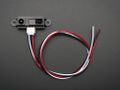
Design Concept 2-Infrared Sensor
This type of sensor is similar to the ultrasonic sensor, however it emits infrared light that is then reflected back. In the same way as the ultrasonic sensor, it measures the time for the reflected light to return in order to determine how far away an object is. This design would also use an array of sensors to map the area around the tricycle.
- These sensors typically have narrower beams than ultrasonic sensors.
- A narrower beam will give the ability for more accuracy.
- However, a narrower beam will also require the use of more sensors to map the desired field.
Design Concept 3-Lidar
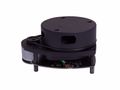
This type of sensor send out pulses of laser light and measures the reflected pulses to determine the location of objects. The sensors are often setup as a rotating system. This would allow us to only need one sensor that will then scan the entire mapping area. The use of this sensor has been discussed as a possibility on previous projects but has been ruled out due to high cost. However, the cost of these systems has been declining over time.
- Sends out laser pulses, so there is no large cone to contribute to larger area.
- The use of lasers means you are only measuring point to point.
- However, since these are readily available in scanning systems the collection of many of these points can lead to a detailed map.
Evaluate concepts/select candidate
Our winning candidate was using the Lidar system. We feel that this system will give us the best precision due to its scanning system. While it would be possible to implement a scanning system with the other sensor types, the system is already implemented with the Lidar sensor. While this option is more expensive, the other systems would also add up in cost with the requirement to have more than one system.
Detailed Design
Description of selected design
The end goal of this project is to have an actual tricycle for a child with visual impairment to ride that will notify him of obstacles that he might hit. To get towards that end goal there are stages in the design that must be gone through first. We need to be able to test the system and gradual get closer to using it as a child with visual impairment would.
The design goal that we are pushing towards now is to use a push cart that is equipped with the RP Lidar and a laptop to receive the data. The RP Lidar is supplied with a software called "Frame Grabber" that gives a graphical output of the data onto a polar plot. We will attempt to optimize the system in this state before moving on further. We will simulate "visual impairment" by blinding ourselves from the outside surroundings with a black covering with the only thing that we can see being the graphical output on the laptop screen.
After refining the system in the state above, we will need to move on to a system with a sensory feedback that is useful to a person with actual visual impairment. We will pursue this through vibrations in the handles that the user holds. Since we are unable to use a child's tricycle we will continue using our push cart. We will eliminate the computer and replace it with a microcontroller that will use the output of the sensor to send the signals to motors placed on the handle of the cart. In this sense, the cart will be our tricycle.
Once the system above has been optimized, an actual child's tricycle system will be pursued. We will equip the tricycle with the RP Lidar, microcontroller, and vibrating motors on the handles. This will require a 3D printed mount to secure the RP Lidar to the front fork of the tricycle. In this case it would be ideal to have a child, preferably with a visual impairment test the system to aid in refinement. A working system in this stage would be the end goal.
Analysis
Describe three types of analysis to be performed on the design
Engineering Analysis 1-Testing Range
Test Purpose:
In this test, we wanted to find the ability of the Lidar to consistently give readings for the distance of an object from the Lidar. We also wanted to determine what the minimum viable distances that the lidar could detect an object of a determined size and shape.
Initial Setup:
Using a tape measure, a straight, flat, and obstacle free section was measured in 1’ increments out to 10’. A 3-7/8” x 5-3/4” box was determined as the object to be used. The Lidar was then placed on the ground at the 0” mark.
Procedure:
After starting the Lidar scanning program, the box was placed at the 6” mark and the data was dumped to a text file. The box was then moved to 1’ from the Lidar and moved in 1’ increments out to 10’. After placing the box at each increment, the output data was dumped to a text file. The box was then moved closer to the Lidar to determine minimum distance that an object could be from it and still be detected. Once this point was determined, the data was once again dumped to a text file. This distance was then measured using the tape measure and recorded. The angle of the box relative to the Lidar was determined using the computer output software. Once the angles of each point were specified, the relative distance measurements were selected and then converted to meters from millimeters.
Results:
Click on the images below to see summary of results.
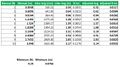
Table of Results
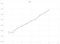
Graph of Error
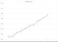
Graph of Error with offset for actual sensor location.
Reflection:
Using the results from the Lidar, we discovered that there is approximately a 1 cm difference per foot. The distance from the receiver to the front of the Lidar was measured to be approximately 24mm. Using this, we could adjust the values from the lidar measurement and lower the error between the Lidar distance and the distance that was measured manually. We determined that the error was small enough to be insignificant, and therefore, the Lidar can be accurately used for obstacle avoidance.
Engineering Analysis 2-Testing on Different Sized Objects
Purpose:
In this test we want to test the ability of the lidar to detect slender objects at longer distances. We thought the the lidar might have problems detecting slender objects at far ranges.
Setup:
Using a tape measure, a straight, flat, and obstacle free section was measured out to 12'. A small section of 1" x 2" (actual .75" x 1.5") wood was used for the test. The lidar was placed at the O mark of the tape measure.
Procedure:
The lidar program was started and then the piece of wood was moved away progressively in 1' increments out to 12'. This was done with both sides of the wood in order to test two different thicknesses. While the wood the was moved out, the graphical output from the lidar was monitored to see if the piece was still visible and how well it showed up (number of data points present).
Results:
The results of this test were encouraging. We were able to see the wood looking at both the wider side and the narrower side of the piece. At about 6' for both sides of the wide, it was noticeable the signal was weaker. However, the signal was still present and clear.
Reflection:
This has a good impact on the project. We worried about the ability of the system to detect these objects and it is good for the system that is able to. It will be helpful to do further testing with different geometries and at speed to see how the results change.
Engineering Analysis 3-Testing Angles to Detect Low Lying Objects
Purpose:
Determine the required angle that the Lidar must be placed at to achieve object detection of an object 4” tall at 4’ to 10’ when the Lidar is placed 15-7/8” off of the ground.
Setup:
The lidar was placed on the cart 15-7/8” off of the ground. An object was placed 4’ from the Lidar.
Procedure:
We adjusted the angle of the Lidar until the object became visible.
Results:
The angle required to detect an object of this height 4’ from the Lidar was too large to achieve a scan of 10’ without detecting the ground first.
Reflection:
The object must have the same height as the height of the Lidar from the ground. Doing this creates problems due to the lack of detection of objects with heights less than the height of the Lidar. To combat this, the Lidar would have to be placed as low to the ground as possible, or a multi IR Lidar would need to be implemented.
Engineering Analysis 4-Testing Different Environments
Purpose:
- We want to analyze how the rplidar will perform in different environmental conditions. We think that common environments that the system could be used in would be:
- A restricted indoor environment such as a hallway or similar area
- An open type indoor environment such as a living room or play area
- An outdoor environment like a driveway or outside play area.
- We think that each of these environments will present different challenges that must be overcome. The purpose of testing each of these environments is to find out how our system performs in these environments and to discover the unique challenges that each environment presents.
Testing Setup:
- All three environments will adhere to the following testing conditions:
- The sensor and a laptop will be placed on push cart as a simulation to a tricycle. At this point the testing will focus on using a graphical output on a laptop as feedback. We will use this to assess and improve the system before moving to a sensory feedback such as touch or sound.
- There will be a “visually impaired” user who is blinded from the outside by placing a black jacket over them allowing them to only see the computer screen in front of them. They will use the outputted graphical data on the computer screen to attempt to navigate the course.
- The course to be navigated will be setup with conditions unknown to the user. The user will blind themselves before being placed in the environment and before any obstacles are setup.
- There will be various group members in the course to act as obstacles, but also to ensure that the system doesn’t get damaged by running into anything.
- These tests will be done at slow walking speeds to get an idea of what navigation is like. Testing at speed will be done in a separate test.
- There will be certain conditions that are environment specific as follows:
- 1. Restricted Indoor Environment:
- This test will be performed in the hallway in the bottom floor of the library. This hallway is 8 feet wide.
- The user will go through a course that is 35 feet long consisting of various obstacles placed in the path.
- The user will attempt to go to the end of the course which will terminate at a dead end after a 90 degree turn. They will then attempt to turn around and navigate the course in the opposite direction.
- 2. Open Indoor Environment:
- This test will be performed in a large open area that has several obstacles placed throughout the room.
- In this test the user will not have an out and back path but will rather roam freely about the room for one minute similar to how a child might ride randomly about a play room.
- The user will attempt to keep moving continuously without crashing into any obstacles.
- 3. Outdoor Environment:
- This test will also be performed in a large open area with obstacles placed throughout the testing area.
- Again, the user will roam freely about the area for one minute with no set path like how a child would roam around on the tricycle outside.
- The user will attempt to keep moving continuously without crashing into any obstacles.
Results:
- 1. Restricted Indoor Environment:
- It was found that it was possible to navigate in this environment with a slight learning curve.
- The main thing that needed to be learned by the user was relating distance on the screen to distance in the actual course.
- On the second attempt we were able to navigate the complete course out and back without hitting the walls or any of the obstacles.
- 2. Open Indoor Environment:
- This testing will be performed in the coming week.
- 3. Outdoor Environment:
- When placed in an outdoor environment during the daytime there was a substantial noise that clashed with the usable data that would be used to navigate.
Reflections:
- Overall, future testing will be done with similar conditions adding the element of speed to see if the user can still navigate while moving at speeds comparable to that of a child riding a tricycle.
- 1. Restricted Indoor Environment:
- We found in this test that navigation is indeed possible in this indoor environment and that it was actually quite easy.
- We found a few things were that problems that will need to be addressed.
- i. The scan that is performed by the rplidar is a planar scan. Therefore, for objects to be detected, they must be at least the height of the mounting point of the sensor. If an object is lower than that it will go undetected. This can be combatted by mounting the sensor as low as possible in the final design.
- ii. Reflective objects were detectable but with less intensity than matte objects. During our test we will were still able to detect and avoid these objects, it was just a phenomenon that was noticed.
- 2. Open Indoor Environment:
- This test will be performed in the coming week.
- 3. Outdoor Environment:
- Due to the noise that was picked up we could not navigate in this environment. Further testing needs to address the possibility of filtering this data to get output that is more usable. Also, testing needs to address the effect of daytime vs. nighttime as well as cloudy days vs. sunny days. Our testing was done on a sunny day.
Video of Lidar Output Compared to Visual
Engineering Analysis 5-Considering The Amount of Relevant Data
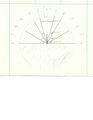
The RP Lidar outputs a large amount of data. This much data sent through a sensory feedback system would overload the user and make feedback unusable. Testing needs to be conducted to determine how much of the this data actually is relevant to send to the user through a sensory feedback system. It is apparent from using the visual output that many of the obstacles that are detected are at an angle or location that user would have to make a hard turn towards to hit. In this case, the user wouldn't need to "see" this object when it is off to the side, however, if they started turning towards, they would then need to be notified. This points towards potentially "zoning" the data into points the user needs to be alerted to and points that can be ignored. Since the sensor will be setup to follow the direction of the handle bars, if the user were to turn towards an object that were being ignored, the object would then come into a relevant "zone" and the system would notify the user. Testing will be conducted in the next two weeks to try to determine what zones are necessary to notify the user of. See the picture below as a conceptual idea to what this "zoning" might look like.
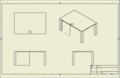
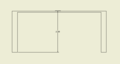
CAD Drawings
With an Arduino Uno, however wiring to Arduino Mega 2560 will be very similar. The Arduino Mega 2560 will be used in order to be able to receive data to the computer at the same time that the RP Lidar is scanning. http://www.robopeak.net/data/doc/rplidar/appnote/RPLDAPPN01-rplidar_appnote_arduinolib-enUS.pdf
Bill of Materials
Projected Bill of Materials to get to working system on tricycle. There will be additions to this after further testing. Many of these items are already available on campus and would not actually be required to be purchased.
| Product | Details | Supplier | Part Number | Base Price | Qty | Price |
|---|---|---|---|---|---|---|
| RP Lidar | 360 Degree Laser Scanner | robotshop.com | RB-Rpk-01 | $336.75 | 1 | $336.75 |
| Wires | Assorted Color Wiring Kit | robotshop.com | RB-Cix-01 | $3.95 | 2 | $7.90 |
| Vibrating Motors | Vibrating Motor Capsule | robotshop.com | RB-Plx-314 | $4.99 | 8 | $39.92 |
| USB Cable for RP Lidar | 120cm A-USB to B-Micro USB | robotshop.com | RB-Dfr-344 | $3.05 | 1 | $3.05 |
| Microcontroller | Arduino Mega 2560 R3 | robotshop.com | RB-Ard-33 | $35.00 | 1 | $35.00 |
| USB Cable for Arduino | 1.5m USB Cable Type A to B | robotshop.com | RB-See-119 | $1.95 | 1 | $1.95 |
| 3D Printed Case | Case to hold RP Lidar | MakerSpace | -- | -- | 1 | -- |
Assembly Instructions
Fabrication Process
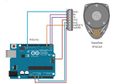
Arduino Mega 2560, vibration motors, and rplidar were wired together as shown in the diagram below. A bracket was 3D printed to attach the rplidar to the tricycle. The bracket was attached to the tricycle with 4 #10-2in machine screws. The program that was uploaded to the Arduino is shown below. Notice that there is an rplidar library that must also be included. This library can be found at this link: http://www.robopeak.net/data/doc/rplidar/appnote/RPLDAPPN01-rplidar_appnote_arduinolib-enUS.pdf
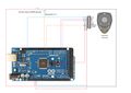
Wiring Diagram
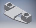
3D Printed Bracket used to attach rplidar to tricycle.
Testing and implementation
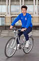
To test the system, we first set everything up onto a push cart because this was more feasible than us riding a tricycle. After much testing a tweaking we moved the system over to the tricycle. The tricycle is too small for us to actually pedal, but we are able to sit on the tricycle and have some push while the blinded driver steers. Testing results were very positive and the blinded driver was able to steer away from obstacles and avoid hitting walls in the hallway.
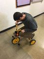
Testing the tricycle.
Photos of Completed design
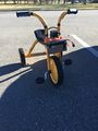
Finished tricycle.
Instructions for safe use
The system can only be used indoors as the rplidar picks up too much noised in an outside environment. Also, while with this system we were able to avoid obstacles, care should still be taken to use the system in a large open space free of obstacles to maximize safety.
Do not use the device unless supervised by an adult that has been fully understood the safe use of this product.
Project Summary, Reflection
This turned out to be a very interesting project that taught us a lot about sensors and Arduino programming. Honestly, in the end the system turned out working better than we were initially expecting. For further improvement, research should be done examining more methods for obstacle avoidance such as the use of the xBox kinect or something similar as this may address the issue of only being able to see objects that are in the plane of the sensor.