Wheel-chair chin-up S15
Abstract
Abstract here - a short statement of the need, findings of project and project outcome.
Melissa Draper talked with us about fabricating a chin-up bar that was fully adjustable to meet the needs of any student that may need to use it, with special regards to a young man in a wheelchair. The chin-up bar would have to be light in order to be moved and stored away easily, full adjustable for heights up to six feet tall, and strong enough to support the weight of a fully grown adult.
Team members

Austin Cantu
Christopher Wininger
Mohammad B Alshaikh Ali
Mohammed Hamad H Alsahli
Sulaiman D Almbuyyidh
Acknowledge help of others
- other
Problem Statement/overview of the need
Melissa Draper requested that we fabricate a fully adjustable chin-up bar for anyone to access and use to exercise. The chin-up bar must be fully wheelchair accessible, be able to support a fully grown adult, and be light enough and portable enough to be easily stowed away in a corner, out of the way.
Design Specifications
1. The chin-up bar must be wheelchair accessible, approximately 3ft of clearance.
2. The chin-up bar must be accessible for students up to 6ft tall.
3. The machine must be light enough that it can be moved.
4. The machine must be able to be easily moved and/or portable.
5. The machine must be able to safely support a maximum average load of 250lbs.
Background research
Our background research began with studying the physics of a chin-up bar and analyzing a simple inverted T-frame bar. This lead to our first conceptual design.
We then took a trip to the gym and analyzed the machines at the Fit. We came across a Smith Machine, which is actually not used for chin-ups, but we started tearing apart the frame and started to like the idea of it. We sat down and searched on the internet for pictures and specifications of various Smith Machines. This lead us to another conceptual design that we fell in love with. The Smith Machine is a very sturdy machine specifically made to hold large amounts of weight and stress. This would be an ideal base design for what we have in mind.
Conceptual Design
Design Concept 1
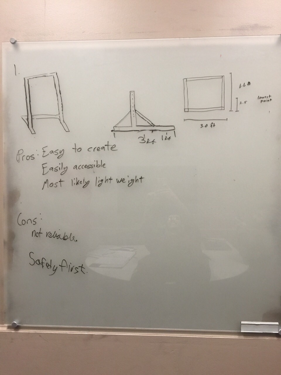
This was our initial design choice. The schematic has a modified T frame with a U beam on the bottom to give it support and to be wide enough to be wheelchair accessible. We added beams attached to the main frame to add stability to the frame as the user does their exercise routine. The frame would be easy to make adjustable if we made the frame itself adjust. The frame would easily be able to be light weight due to the lack of material involved with this design.
Problems consist of the beams added to the main frame for stability would be great for people that could use the bar up to a certain height. Once that height is exceeded, major stress begins to form on the beam because of the limited support given. Safety is our number one priority. Stress fractures could easily form after multiple uses.
Design Concept 2

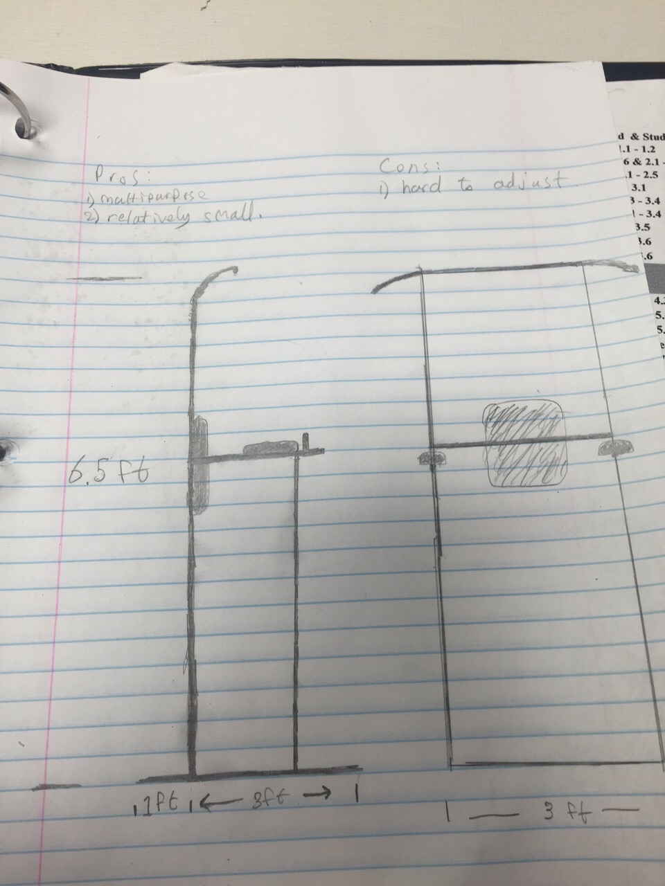
This was the second design idea we agreed on. This is a general modification of our first design choice. This design would again easily made light weight. It would be easy for people to use. Very cost effective as well.
When we thought about tampering with the design and adjusting to our specifications needed for the wheelchair, we decided that it would most likely become too unstable and the modifications would become too complicated for what it was worth.
Design Concept 3
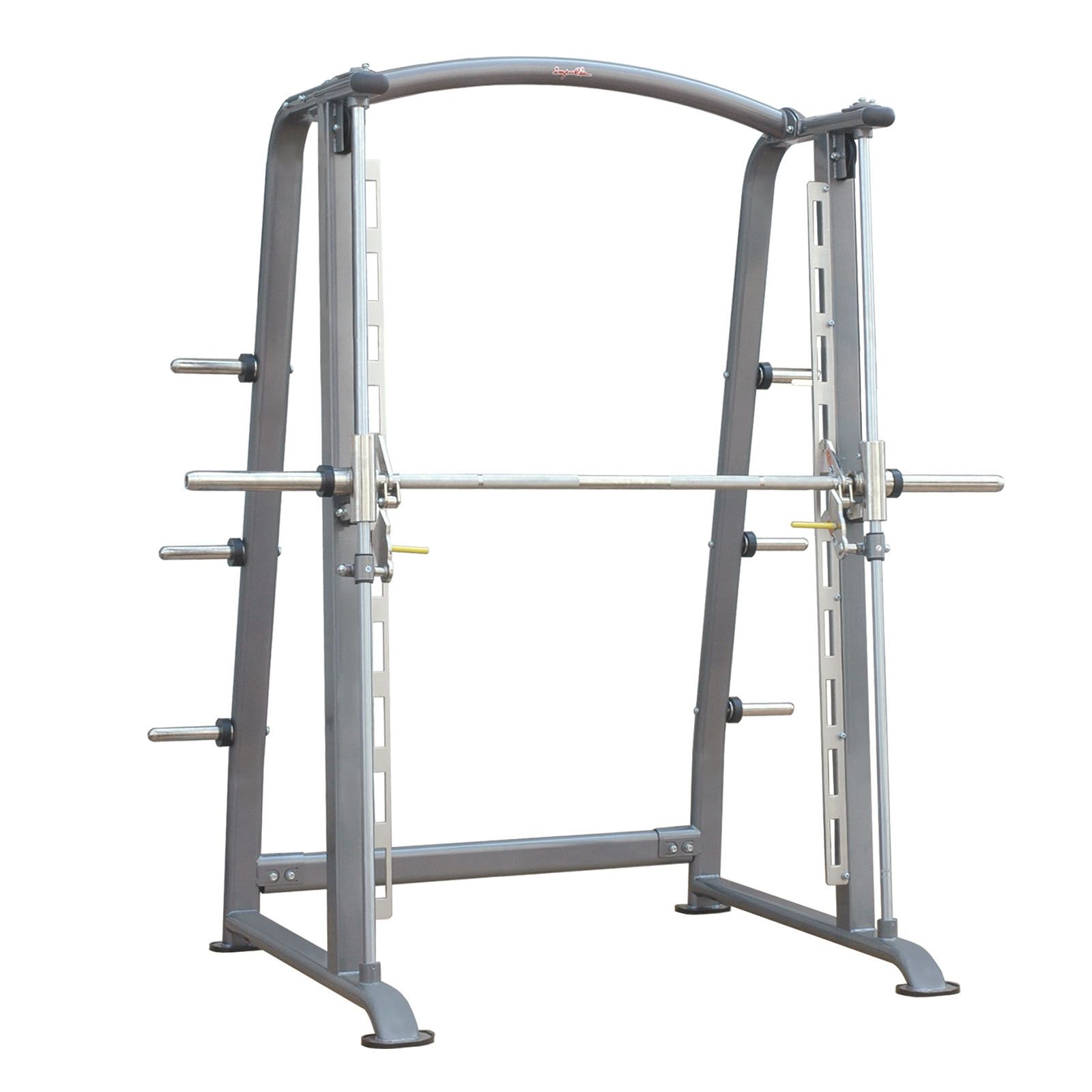
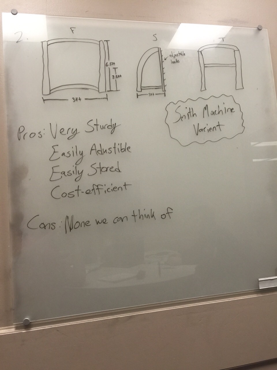
We sat down and did research and one of our members were mentioning ideas about possibly modifying a Smith machine from the gym. The machine is very capable of withstanding heavy loads. The machine is already designed to be adjustable to hold the weights. The Smith machine has a wide base capable of easy modification for wheelchair accessibility. We have chosen this to be our main design to modify.
The chin-up bar variant we intend to design will have a similar body frame with a slightly wider base. The machine will be made taller, accessible for adults up to six feet tall. The bar will be completely adjustable with an intended adjuster similar to the picture shown above. The bar will have a hook on either end attached to a pulley system. The hook will run through a slider as the user lifts the bar up to adjust it higher and as the hook gets to a certain point, it will fall through the slider and be able to support from that section. If the bar is to be lowered, the user can pull the hook outwards and easily slide the bar down to the height intended. The frame will also be modified to allow simple breakdown of the machine for easy storage. Due to the design of the machine, it is designed for strong support and able for low weight. In the rear support bar nearest the ground, there will be wheels inserted into the bar so that the machine can be tilted on its end and easily rolled for easy mobility.
Evaluate concepts/select candidate
Use a decision matrix or similar tool to compare designs against project specifications Discuss winning candidate
Detailed Design
Description of selected design
After deliberation and weighing the pros and cons of all choices and ideas that came to our minds, we decided to build the variant to the Smith Machine. This design will be able to withstand large amounts of weight while remaining portable when necessary to store away, yet sturdy and immovable while working out.
Detailed description of selected design
Our final design consists of a rectangular frame made of aluminum. The aluminum is lightweight, yet able to withstand good amounts of stress. The bottom of the frame will be made of steel, in order to keep a heavy base, as to not let the machine tip over while someone is using it. The steel and aluminum will both have telescopic tubes implanted in the sides and held together by a pin to allow for quick, interchangeable storage. The aluminum frame will also have a telescopic tube placed inside the steel frame and held together with a pin. There will be approximately nine hooks welded onto the frame on the inside of the machine for different heights if people to be able to use the machine. The chin-up bar will be made out of steel tubing and will be attached to a slider bar going vertically into the tops and bottoms of the frame. The chin-up bar will freely slide on this bar, keeping the bar from falling off the machine. The chin-up bar will also have a mechanism connected to it in order to grab a hold on the hooks. With this design, the bar will not be able to slide side to side as the user is working out. Wheels will be implanted on the back side of the machine. The machine will be slightly heavy so the wheels will act as a way to move the machine when necessary. The wheels will be set so that the wheel only makes contact with the floor when the machine is tilted onto the wheel. This keeps the safety of the user in tact and not at harm from the machine sliding.
Analysis
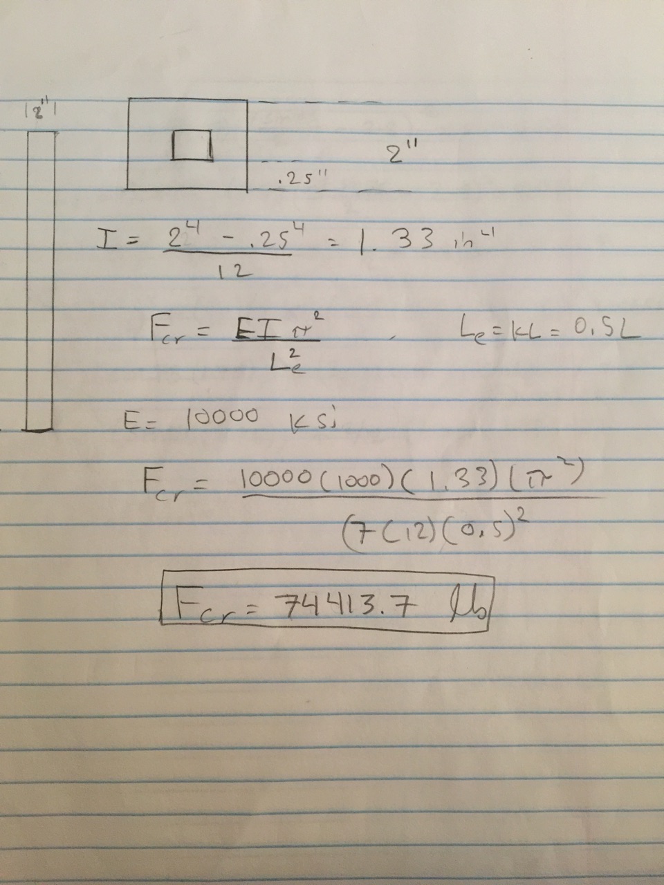
Engineering analysis 1
Engineering analysis 2

Engineering analysis 3

Engineering analysis 4

CAD Drawings
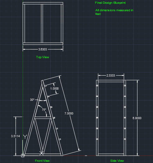
This is a CAD drawing of our final design overall.
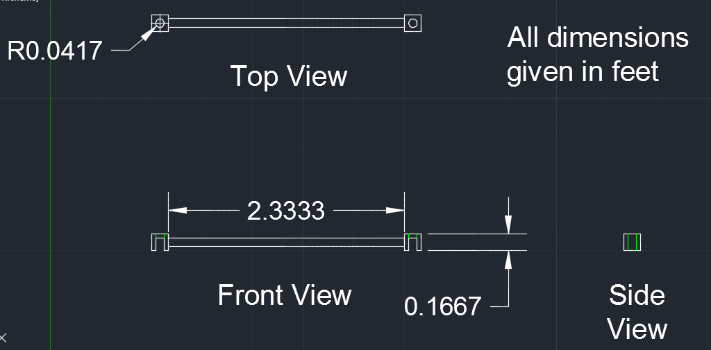
This is a drawing zoomed in on the bar and how we are going to weld the pull-up bar to attach to the pins on the machine.
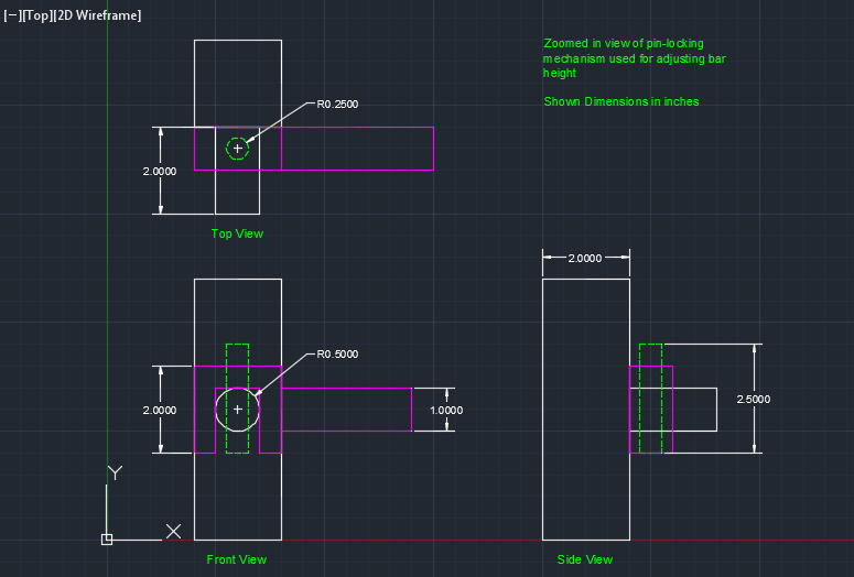
This is a drawing showing how the pins will slide into the pull-up bar, locking it in place.
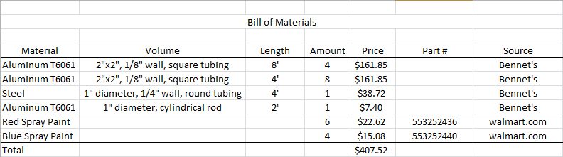
Bill of Materials
Assembly Instructions
To start fabrication on the machine, the first thing we decided on was to cut the aluminum rods into 4" pieces to make into the pins. Next, we drilled holes into the 8' aluminum frame pieces to fit the pins into. We cut 1' off of the frame pieces. We proceeded to cut the other aluminum pieces to size in order to start welding the frame together. We welded the frame together. We then drilled a hole into a steel square tube and cut one side of it off in order to create the U-piece shown in the diagram above to rest on the pins and to lock them in place.
Fabrication Process
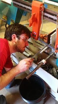
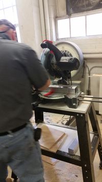
This is a picture of us cutting the aluminum rods
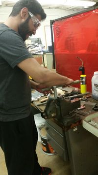
This is us filing down the pins so they are smooth
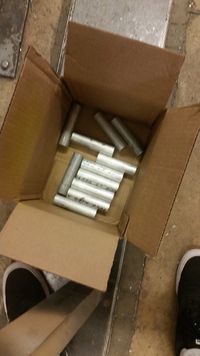
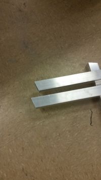
This is the finished product of cutting the pins
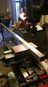
This is the frame prior to drilling the holes for the pins
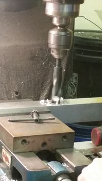
Drilling holes
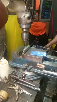
Drilling holes into the pins
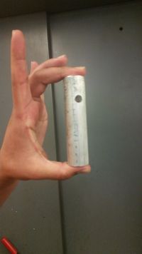
Finished pins
Cutting the aluminum frame pieces at an angle to be flush with the ground
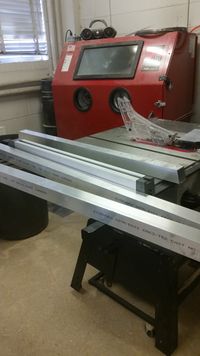
Frame pieces done
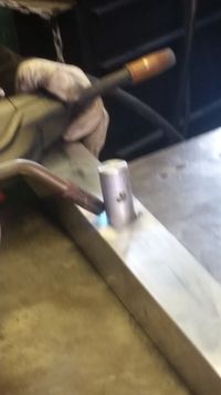
Welding the pins
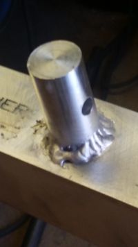
Pins welding done
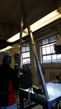
Welding the frame
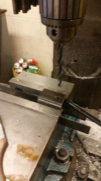
Drilling holes into the steel U-pieces
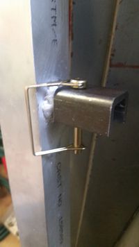
Making sure the U-piece fits securely on the pins
Testing and implementation
Describe testing, delivery, how used/received by the family
Photos of Completed design
Insert pictures of the final product
Instructions for safe use
Provide a clear summary of safe use for the family. Do not use the device unless supervised by an adult that has been fully understood the safe use of this product.