Wheel Chair Assist
Abstract
The goal of the wheel chair assist project is to design a machine that will extend the available reach of a child in her wheelchair.
Team members

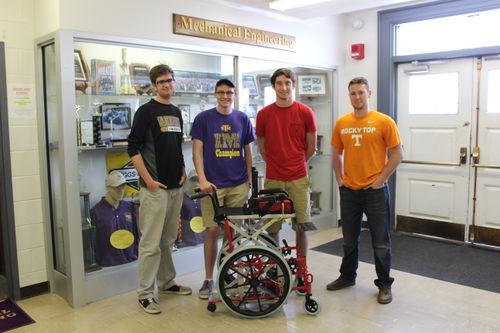

Clay Isom, Robert Myers, Mitchell Henderson, Matthew Braisted, Yousef Alzufairi
Problem Statement / Overview of the Need
The goal of the wheel chair assist project is to design a machine that will extend the available reach of a child in her wheelchair. The device will be an adaptation of the pre-existing wheelchair, easing the many difficulties faced by the child and those who help her. This is to be done with the intention of not dramatically changing her current environment.
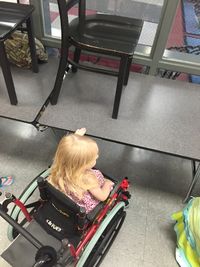
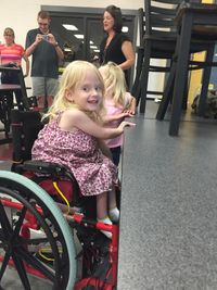
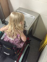
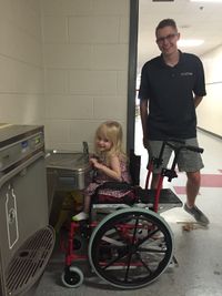
The child is 5 years old and does not have the use of her legs because of her spina bifida. She needs to be able to reach things like the water fountain and classroom tables that she currently can not reach. In addition to this, raising her up will allow nurses to easily move her from the chair to the changing table.
Design Specifications
Reach Our design specifications for reach will include the need to reach distances between 22.5" to 32" relative to the ground.
Safety This is a very important part of our design considerations. The child will need to be help by a restraint device like a seat belt. Along with that we need for our design to include systems in place for safety after loss of power.
Weight Another very important part of our design considerations is the overall weight of the chair. The mother of the child needs for the wheelchair to not increase dramatically in weight because she needs to be able to lift it and carry it up stairs.
Performance The child weighs around 50 pounds so the mechanism needs to be able to easily lift her consistently without her doing any work to do so.
Background research
Our background research was mainly focused on lifting mechanisms. We did research in the relative size area of a wheelchair found many useful concepts and ideas associated with lifting.
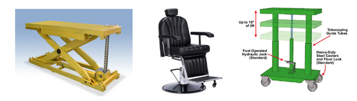
Another element of our background research was visiting the school our client attends. We saw her current wheelchair and toured the school to see exactly where our design would be put to use. In meeting and interviewing our client and the school nurse, we gained valuable information about design needs and problems that they are currently facing.
Conceptual Design
Design Concept 1
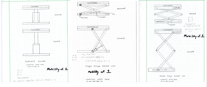
1) Hydraulic Cylinder:
In this design a hydraulic pump would cause a fluid to flow, creating pressure, in order to move the rod, a component of the hydraulic cylinder. Essentially the rod would experience displacement due to the pressure exerted by the pump, raising and lowering the seat of the wheelchair.
Design Concept 2
2) One Stage Scissor Lift: In this design, a scissor lift assembly is used to lift the seat of the seat of the wheelchair. A linear actuator, drawing from a power source, displaces linearly, pushing a slider at the base of the lift to start the process.
Design Concept 3
3) Two Stage Scissor Lift: This design is similar to design concept two. However, the addition of the second stage provides further stability as well as providing an increase in lift height and ease of use.
Evaluate concepts/select candidate
Decision Matrix: All ratings are out of 5 based on how the design meets the need of each category. The highest ranking in each category includes: low sound level, lift of 12 in.-18 in., speed near 1 in./s, low cost, low weight, low maintenance, very safe, and high aesthetics. Because of its high total percentage in terms of rank in each category, the two stage scissor lift (Design Concept 30) was chosen for this project.
| Concept 1: Hydraulic Cylinder | Concept 2: One Stage Scissor | Concept 3: Two Stage Scissor | |
|---|---|---|---|
| Sound Level | 2 | 5 | 5 |
| Lift Height | 5 | 4 | 5 |
| Speed | 4 | 4 | 4 |
| Cost | 2 | 4 | 4 |
| Weight | 3 | 4 | 4 |
| Maintenance | 2 | 4 | 4 |
| Safety | 3 | 4 | 4 |
| Aesthetics | 3 | 4 | 4 |
| Ease of Use | 2 | 4 | 5 |
| Total/Possible | 26/45 | 37/45 | 39/45 |
| % Total | 57.8 | 82.2 | 86.7 |
Detailed Design
This section will describe a detailed design process
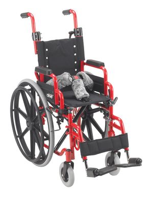
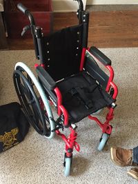
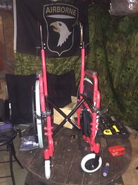
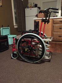
Wallaby Pediatric Wheelchair
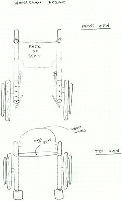
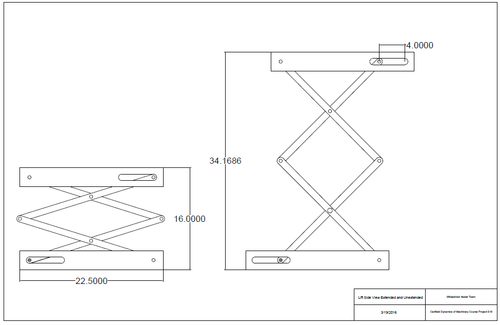
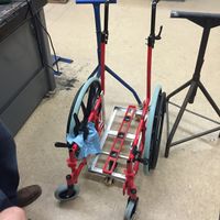
The Wallaby Pediatric Folding Wheelchair, made by Drive Medical, is the platform of which we will build upon to enhance the chair to our uniquely detailed design specifications. The collapsible portions of the wheel chair will be removed and along with the crossbars underneath the seat. The drawing below shows the wheelchair with parts removed to be used as the frame of the design.
Description of selected design
The decision on our final design was based on all aspects important to this project such as sound level, lift height, speed, cost, weight, maintenance, safety, aesthetics, and ease of use. By analyzing all of these characteristics of the different designs, we concluded that the two-stage scissor lift design was the most competent in each of these categories.
Detailed description of selected design
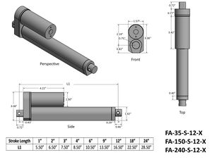
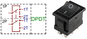
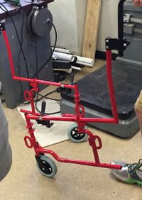
Our final design consists of a two stage scissor lift mechanism powered by a rod type linear actuator. The actuator will be a total of 10.5" long and have a stroke length (length of extension) of 6". Then, using the onboard limit switch we will reduce the stroke length to 4" for our desired maximum lift height of 18". The linear actuator will be attached to the bottom of one of the scissoring links and slid up and down a track to induce an upward lift. The linear actuator will be wired to a DPDT (double pole double throw) momentary toggle type switch which will allow one two displace the linear actuator upward and downward as well as cutting off the motor whenever the switch is released. Our circuit will then be powered by a 12V Lead-Acid type battery which will be permanently hooked to a battery charger allowing it to charge the battery by simply plugging in a single power cord into a wall outlet.
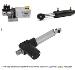
Linear Actuator:
DPDT Circuit Schematic:
CAD Drawing of Final Design Concept:
Analysis
Three Types of Engineering Analyses Performed: Circuit Analysis Powering the Chair Movement, Mechanism Model of Lift, and Force Analysis
Circuit Analysis
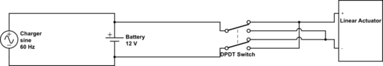
Circuit Features:
1) Charger: Energizer 12V Smart Charger with charge current of 2A, Input Frequency of 60Hz for operating temperatures ranging from 32-104 degrees Fahrenheit. Its
2) 12V Battery: Fergelli 12V Lead Acid type battery with capacity of 7Ah
3) DPDT Switch: Fergelli rocker style DPDT momentary switch with built in limit switch. Switch has a contact rating of 15A at 12V DC and changes between 2 sets of poles to extend and retract actuator.
4) Linear Actuator: Fergelli 12V Linear Actuator with a pull force of 200lb draws 5A of current
-Using this data, our total use time per charge on the battery would be 7Ah/5A= 1.4 hours.
-In terms of charge time on the battery using our smart charger: 7Ah/2A= 3.5 hours
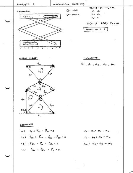
Mechanism Modeling Analysis
Below is our Mechanism Modeling Analysis. As we learned in class, Mechanism Modeling is a five-step process where you can check several important elements including: mobility, vector modeling, unknowns, equations of compatibility and individual loop equations. Our mobility checked out at 1, and there are only three separate unknown angles (while the lift is, either, at rest or in motion) due to the steady input that our actuator will provide.
Force Analysis
The Force Analysis involved the load weight, the weight of the bars of the scissor lift, and the force of the actuator on the base of the lift. The analysis was done with given information, estimations of loading and materials used, in order to evaluate the required force of the actuator at full extension of the lift as well as when the lift is retracted. This analysis lead to the selection of the linear actuator that will be used.

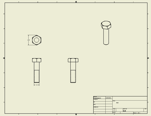
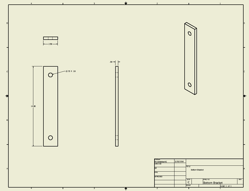
Bill of Materials
| Quantity | Item | Description | Source | Price |
| 1 | Wheelchair | Wallaby Pediatric Folding Wheelchair | Amazon.com | $265.26 |
| 1 | EcoWorhty Linear Actuator and Wiring Kit | 6" Stroke, 200lb, Rod Style Linear Actuator | Amazon.com | $91.95 |
| 1 | 12V Battery | 12V DC Lead-Acid Type Rechargeable Battery | Amazon.com | $22.73 |
| 1 | 12V Smart Charger | 1.1A Charge Rate Battery Charger | Amazon.com | $36.55 |
| 4 | Double Sealed Ball Bearings | (1/2) ID, (1&1/8) OD | McMaster Carr | $35.00 |
| 4 | Sleeve Bearing | (1/4) ID, (1/2) OD | McMaster Carr | $3.64 |
| 13' | L-Bracket | McMaster Carr | $29.75 | |
| 8 | Aluminum flat bar | 2' x (1/4) x 1 | McMaster Carr | $40.24 |
| 1 | Aluminum flat bar | 1' x (1/8) x 2 | McMaster Carr | $2.25 |
| 8' | Aluminum flat bar | (1/4) x 1.5 | McMaster Carr | $21.33 |
| 12 | Shoulder Screw | 1/4" x 3/4" | McMaster Carr | $11.40 |
| 20 | Sleeve Bearing | (1/4) ID, (3/8) OD X 1/4" thick | McMaster Carr | $15.20 |
| 2 | Sleeve Bearing | (3/8) ID, (1/2) OD X 1/2" thick | McMaster Carr | $1.14 |
| 3' | Rod | 4140/4142 Alloy Steel 1/4" Diameter | McMaster Carr | $10.71 |
| 1' | Rod | 4140/4142 Alloy Steel 3/8" Diameter | McMaster Carr | $3.17 |
| 10 | One-Piece Clamp-on Shaft Collar small | 1/4" Diameter, Black-Oxide Steel | McMaster Carr | $19.10 |
| 2 | One-Piece Clamp-on Shaft Collar big | for 3/8" Diameter, Black-Oxide Steel | McMaster Carr | $3.82 |
| 1 | 2" thick foam | Hancock Fabrics | $10.52 |
Current Total: $623.76
Assembly Instructions
After completing the design phase the goal was to build the design. The building process involved time in the mechanical engineering machine shop at Tennessee Tech as well as assistance with machine use and design functionality from Dr. Steve Canfield and Jeff Randolph in the shop.
The procedure for assembly included:
1. Drafted Bill of Materials and material purchasing through the ME department at Tennessee Tech
2. Disassembled the purchased wheel chair and removed all add-ons and other parts of the original chair that would not be used in the final design.
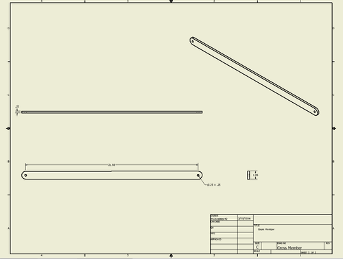
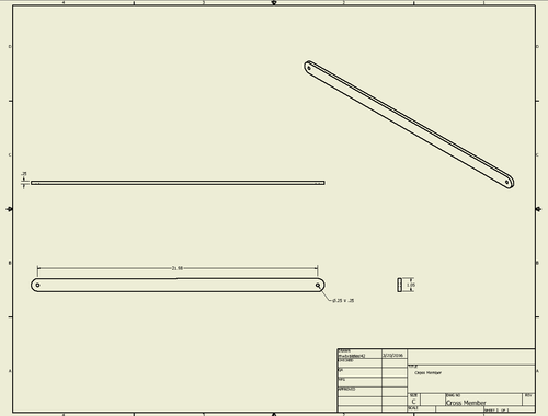
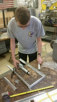
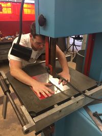
3. Cut all aluminum L-brackets and cross bars to length using the industrial lubricated bandsaw
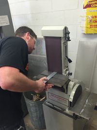
4. Rounded edges of each aluminum cross bar using the sanding machine
5. Reamed holes at each edge and center of the aluminum cross bars
6. Pressed on-size bushings into the reamed holes
7. Pressed sealed bearing at one end of four of the bars, serving as rollers for the lift
8. Sanded and Welded together L-bracket pieces to create rectangular frames for top and bottom of lift
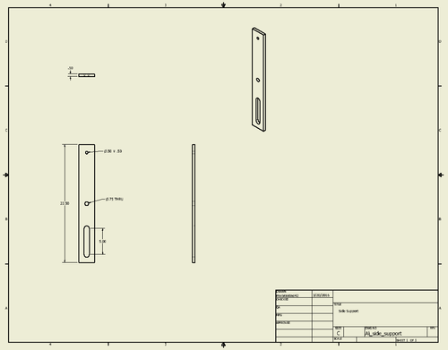
9. Cut aluminum flat bars for supports by which the lift will connect to wheelchair frame
10. Sanded and welded together the bottom frame and support flat bars
11. Grinded off handle bars of wheelchair frame
12. Sanded wheelchair frame and handle bars
13. Welded metal tubing to wheel chair frame and then to handle bars to extend the frame and re-attach handle bars
14. Painted wheelchair frame
15. Sanded and welded a cross bar between handle bars to minimize frame flexing
16. Used a drill press to put holes in chair frame and flat aluminum supports
17. Used countersink bolts to attach lift frame to wheel chair frame
18. Used a grinder to chamfer flat bar edges and minimize the lift frame bumping the wheelchair frame
19. Cut 3/8 in. diameter rod to length using bandsaw
20. Ran 3/8 in. bar through two of the bearing/rollers and the linear actuator rod
21. Used clamp collars to prevent movement of the bearings along the rod
22. Cut 1/4 in. diameter rods to length
23. Ran 1/4 in. rods between the linkages of the lift in two places for support
24. Prevented sliding using clamp collars
25. Assembled aluminum cross bars using a shoulder screw, a spacers, and a nut at each linkage that didn't have a supportive rod
26. Attached top of frame for lift
27. Cut steel tubing to length, bolted a desk chair wheel to it and attached it to the wheelchair frame as a rollback bar
28. Sanded arm bars from original chair and weld them with steel tubing to create the seat back and arm rest
29. Attached arm bar assembly to wood board using thread spacers through round holes in the wood
30. Attached board to to top frame of lift and placed original seat and seat back onto arm rest and seat back frames
31. Cut sheet metal to length and bend using a 90 degree angle surface
32. Painted this piece and attached with seat assembly as the footrest
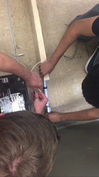
33. Connected all wiring from the actuator to the battery to the charger and mounted in a box on the chair
34. Cleaned and polished the frame
35. Tested the lift with various methods
36. Delivered the Chair to Stone Elementary School
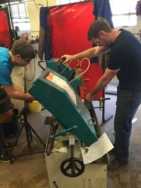
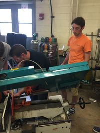
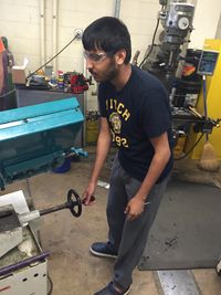
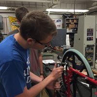
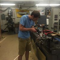
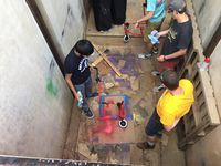
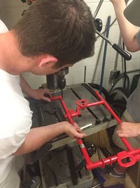
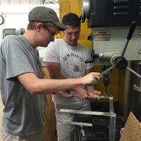
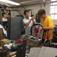
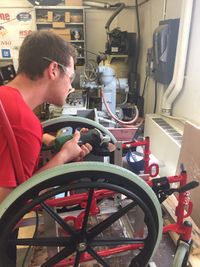
Fabrication Process
Wheelchair Frame
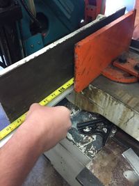
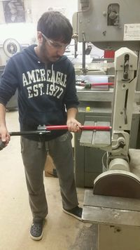
Cutting aluminum with a bandsaw
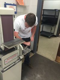
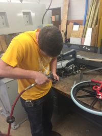
Rounding the rod edges with a sanding machine and pressing bushings into holes in the bar
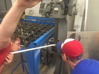
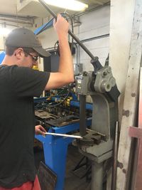
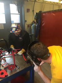
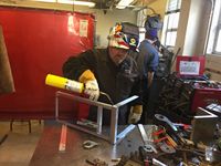
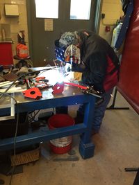
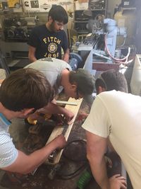
Cutting the wheelchair steel and sanding pieces for welding
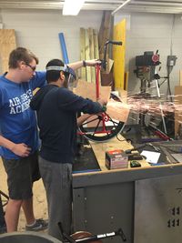
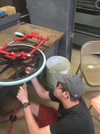
Shout out to Jeff Randolph for helping with the welds!
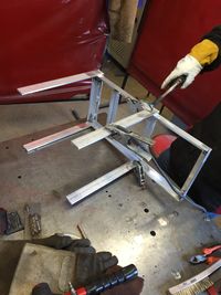
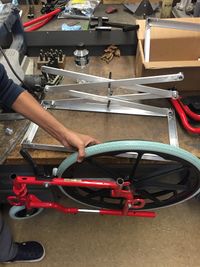
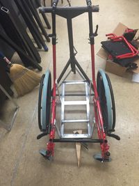
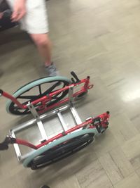
Assessing the wheelchair frame assembly and painting side bars
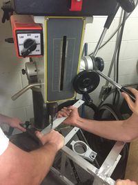
Using a drill press and mounting aluminum frame to wheelchair frame
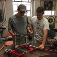
Assessing the wheelchair frame and lift frame
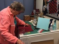
Matthew's grandmother sewing the fabric for the seat
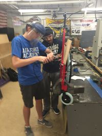
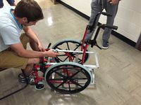
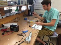
Robby working on wiring. Clay cutting metal for the footrest piece
Testing and implementation
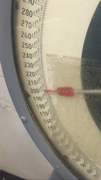
The actuator was texted using 200lbs of weight, pushing it along the floor.
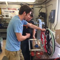
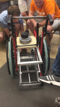
The lift was tested at multiple stages in assembly, assessing its behavior with weight applied
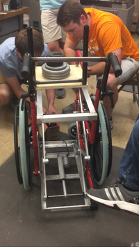
The chair was also tested at the Tennessee Tech Child Development Lab. Special thanks to the CDL for allowing us to have a three year old child sit in the chair and test the lift.
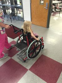
Finally, the chair was delivered to Lauren at Stone Elementary School.


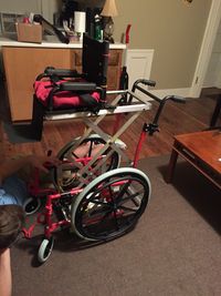
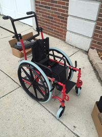
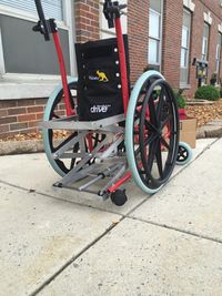
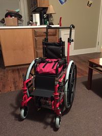
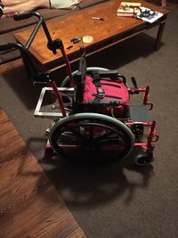
Photos of Completed design
Instructions for safe use
Download and unzip file to read the instructions for safe use. File:Instructions for Safe Use Wheelchair Assist.zip
Project Summary, Reflection
We, the wheelchair assist team, are very proud of what we have accomplished this semester. By the numbers, the five of use spent, on average, 97 hours each from start to finish. Thats a total of almost 500 man hours. We were more than $700 under the total amount spent on the comparable design completed in 2014. And, we completed the project 5 days ahead of schedule. Looking back at the beginning of the semester, we had no idea the massive undertaking we agreed to. We chose this project out of a list of about 10 because we believed we could truly make a difference by taking on this challenge. We also felt like it would play to some of our strengths. What we could not have predicted was the amount of learning that would take place, the amount of times we would fail, the amount of hours we would be in the shop, or the amount of times we needed to ask for help. We would also like to make the following acknowledgments: First and foremost we would like to thank Jeff Randolph. Specifically for teaching us, being patient with us, working late, working early, and encouraging us. Likewise, we would like to acknowledge Dr. Canfield who gave us this incredible challenge and the ability to make something that we are tremendously proud of. He has given us the chance to use our talents and time to make a difference for a very special young girl. We would also like to thank Matthew’s grandmother, Mary Webb, for sewing the custom seat by hand. Finally to our friends, family, and peers who encouraged us, gave us ideas, and voiced concerns. Thank you for taking the time to see our work and read the website.