Wheel Chair Phone Attachment F14
Abstract
Brooke Malone lives with Scoliosis which is an abnormal curvature of the spine. This disease severely limits her upper extremity mobility. Normally the legs are most effected, but in Brooke's case she also has limited mobility of her arms.
Team members
- Michael Travis
- Salim Aldossary
- Saad Alhogbani
- Jared Davis

Group Pic
Problem Statement
Brooke Malone needs a device that will at the very least allow her to use a cell phone without holding it to her ear with her own hands and will easily attach to her wheelchair.
Design Specifications
1. Must be retractable and out of the way when not in use.
2. Will add mobility via mechanism to a single human input.
3. Must be Ergonomic.(Easy to Use)
4. Must be Poka-Yoke. Japanese word for "mistake proof".
5. Will provide multiple ranges of motion.
6. The device must be removable.
7. Will be the lowest competitive cost possible.
8. Will be able to hold multiple devices of different sizes.
Background research
There are many devices on the market today, in fact many under $100. One of the disadvantages of these devices is that the end user cannot be fully independent when using the device. Someone has to help the end user to set up the device.
Conceptual Design
Summarize your conceptual design process. Develop at least three concepts.
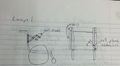
Design Concept 1
This design is much like a scissor lift mechanism. It will be a 4 bar or 6 bar linkage combined with a pinned mount to allow the freedom to rotate toward and away from Brooke's ear. There will have to be some kind of spring or screw possibly to allow for alignment.
PRO's
- Easy to construct and assemble
- Removable
- Easily concealed when not used
- Can be used with multiple devices
CON's
- Limited Mobility
- Can get things stuck in it.
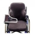
Design Concept 2
This design is much like a stadium seat student's desk, as in Prescott Hall 215. The armature attached to the seat rotates and folds back away from the user when not needed. This is more complex than Design 1, but allows for more creative design.
PRO's
- Plenty of Mobility
- Removable
- Can be used independently with no assistance.
- Can be activated with multiple inputs.
CON's
- More Complicated Mechanism
- May not be able to conceal on wheelchair very well
- It may be awkward to use.
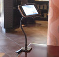
Design Concept 3
This design utilizes what is already used in the market today. It is much like a lamp stand that is semi-rigid that is "snake-like" and can be turned to virtually any angle or length needed to achieve its purpose.
PRO's
- Amorphous shape (semi-rigid)
- Removable
- Most degrees of freedom
- Can be used with multiple devices
CON's
- Reliability
- Will need assistance to use.
Evaluate concepts/select candidate
Use a decision matrix or similar tool to compare designs against project specifications Discuss winning candidate
| Design 1 | Design 2 | Design 3 | |
|---|---|---|---|
| Mobility | 2 | 3 | 4 |
| Ergonomic | 3 | 4 | 2 |
| Manufacturing Simplicity | 2 | 2 | 3 |
| Functionality | 2 | 4 | 3 |
| Cost | 3 | 2 | 3 |
| Reliability | 3 | 4 | 1 |
| Durability | 3 | 4 | 1 |
| Additional Uses | 1 | 4 | 1 |
| Total | 19 | 27 | 18 |
| Possible | 40 | 40 | 40 |
Detailed Design
Knowing that Brooke has a limited range of motion with her arms we have decided to incorporate a headset into the selected choice design. This improvement will allow her to have full mobility of the upper body without the mechanism becoming an inconvenience, without adding too much additional cost, and without limiting but increasing the functionality of the mechanism. We've also decided the most reliable and appropriate input for the mechanism should be a linear actuator powered via battery pack. This input also requires us to design a device that will position the wheelchair cell phone holder in the correct useful location, which is directly in front of Brooke and where she can use the phone easily. This will be much like a tray you would find in a teaching auditorium.
Description of selected design
This design will utilize some concepts that are currently on the market but fairly expensive and they don't contain the usefulness of a combined mechanism. We will use a tray made of polycarbonate to fix a phone holder on the wheelchair that will allow Brooke to use the phone via a headset that will be retractable from the front of a wheelchair by means of an battery powered linear actuator mounted to the wheelchair to properly position the tray in front of her for use. The tray will be positioned in a track with linear bearings so that the input can be controlled to give the desired path of motion when activated. A spring and hinge will be used in concert with the input to pull the tray downward toward Brooke's lap. The spring was chosen because of safety reasons and protection of the device so there is not excessive force applied that could damage the device. The tray will also need a roller/slider to guide the tray above the armrest of the wheelchair and not damage it as the tray moves into position. This device can have several other uses besides holding a cell phone.
Detailed description of selected design
polycarbonate tray
.png/78px-Screenshot_(2).png)
Tray Dimensions
We decided to use the same material for the tray as most suppliers of tray attachments and that is polycarbonate. Polycarbonate is very durable and fairly inexpensive, considering the amount of strength that it has compared to other plastics. Wood was also an option, but it is prone to scratch, deform, and splinter over time. An example of a polycarbonate tray is shown above. Our tray has significant advantages to the one pictured because we have added a degree of freedom with our mechanism and will not require the user to manually flip over the tray to move it out of the way when not using it.
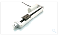
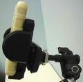
linear actuator
Our linear actuator will be similar to the one pictured. We have selected an actuator from Firgelli Automations that is capable of lifting 35 pounds and a static load limit of 70 pounds, has a speed of 2 inches/second, and has 15 inches stroke length. This should be more than enough capacity for the weight of the tray, the linkage, and the time to deploy when she has a phone call.

Headset
Since, we will not be carrying the phone directly to Brooke's ear and having a mechanism that would difficult to contend with we've added the headset as a component and will be similar to the one pictured above. This gives her the complete freedom of her head and neck area and not something obtrusive into that space.
Analysis
Three analysis performed on the project:
- The loads analysis on the hinges that will carry the weight of the tray and additional loading from the user.
- Linkage analysis of the input device that will activate the tray into position.
- Battery life cycle analysis.
Engineering analysis 1
The load encountered on the hinges is a combined load of transverse shear and pure bending. The load on the hinge pins are shear force loads. The combined loads of the tray and user cannot exceed that of the maximum load of the linear actuator, 70 pounds. The furthest moment arm from the hinge is 10 inches away. The dimensional requirements of the project for the hinges:
- 2" x 3/4" rectangular hinge
- 1/4" hinge pin
- 9 gauge (.1495 ") steel rectangular frame wings
In static equilibrium, the 70 pound load will have to be held by 2 hinge pins that are 3 inches/pin in length. The pins will also have a 700 inch-pound moment to support. The pins specified for use were 1/4 inch diameter. So, a simple shear stress calculation was done to determine the safety factor of the specified dimensions, assuming a mild steel hinge pin.
Equations Used:
- df
- fg
Results:
- FOS=
The frame wings will endure the same forces but across the area of 2 inch by .75 inch. The same shear stress calculations were performed on the frame wings. However the frame wings also are in pure bending because they are fixed and denied the freedom to rotate, so an added normal stress calculation was performed to the frame wings.
Equations Used:
- ddf
- ag
- fg
Results:
- FOS=
After researching and buying 2 hinges, it was determined that a common hinge of proper dimensional size could not withstand the load of the tray. Most hinges this small do not specify a load rating. For this reason we made our own hinges, so we could control the safety factor of the hinge.
Engineering analysis 2
The linkage that will move the tray into position is a four bar linkage that translates forces and movement from the lift provided from the actuator to the tray. Dimensional requirements constrain the mechanism to fit in a 2 inch by 3.5 inch by .75 inch space. Because of the constraint and ease of fabrication, a slider mechanism will be used to translate force and movement to the tray. Other than the dimensional requirements, the mechanism output is vertically linear and has a movement of .75 inches. Through the design of the mechanism, several iterations of linkages were tried to find one that best fit our use. The links as found to be best suited were:
- ternary link with a pivoting joint from ground
- slider link with a round pin for contact to ternary link
- basic link of variable length between 3.33 - 4.33 inches
- ground link
Without adding any lever mechanical advantage (1 to 1 lever), the ternary link will serve as the input from ground to the slider and its pivot is 1 inch above horizontal ground and in the center of its length. Its length will be the full 2 inch width of the mechanism. The slider will slide relative to ground and follow a strictly vertical path. The output mechanism will be a gas spring that we are considering rigid and will travel the full vertical displacement as the slider and will link the slider to the pivot of the tray that returns the mechanism to ground. With this knowledge we were able to solve for the slider's length that would satisfy the constraints. When assuming the gas spring is 3.33 inches in length, the slider's length should be ?.
Engineering analysis 3
The battery used for this project is the Universal UB12120, which is a 12 V DC Sealed Lead Acid battery. It can also be used for many different applications including medical equipment, alarm systems, and lighting applications. The capacity of the battery is 12 Ah and it is used with a motor that generates a maximum of 5.68 A for at least 2.1 hours on one charge. The battery weighs about 9 lbs, and it has a length, width, and height of 5.95, 2.9, and 3.7 inches respectively.
A 3-position toggle switch is used to connect the battery to the drive motor. The switch carries 25 A at 12 V DC and snaps into a 0.838 x 1.45 inch square hole, and it automatically turns off when released. The wiring used in the circuit is 18 gauge PVC coated wiring that can transmit 17 A at 86 F.
The battery can be charged with a 12 V, 2 A charger, and it only takes 6 hours to charge after being completely depleted. It is a lightweight charger and can be mounted on the wheelchair so that it can be charged overnight and used again the next day.
CAD Drawings
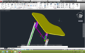
Overview
.png/120px-Assembly_(1).png)
Assembly 1
.png/120px-Assembly_(2).png)
Assembly 2
.png/120px-Assembly_(3).png)
Assembly 3
Bill of Materials
qty, item, description, source, part number, price
| qty | item | description | source | part number | price | |
|---|---|---|---|---|---|---|
| 1 | polycarbonate sheet | 12"x24"x.375" | US Plastics | 43051 | $31.90 | |
| 1 | Headset | Cell Phone Headset | Office Max | 388858 | $18.99 | |
| 1 | Linear Actuator | 15" | firgelliauto.com | FA-35-TR-15" | $119.99 | |
| 1 | steel round tubing | .5" x .120" x 72" | metalsdepot.com | T212120 | $28.44 | |
| 1 | steel round tubing | .75" x .120" x 24" | metalsdepot.com | T234120 | $10.90 | |
| 1 | steel flat | .5" x .120" x 24" | metalsdepot.com | F11812 | $1.36 | |
| 2 | linear bearings | .5" I.D. bearings | McMaster Carr | 9533t3 | $15.24 each | |
| 1 | roller bearings | 6mm I.D. bearings(10 pack) | vxb.com | 696ZZ10 | $24.95 | |
| 2 | bolts | .25" x 1.5" | Lowes | $6.50 | ||
| 1 | hinge | 2 pack of hinges | Lowes | 308971 | $2.38 | |
| 1 | gas spring | McMaster Carr | 9417K1 | $41.55 | ||
| 1 | torsion spring | 1800 torsion spring | Grainger | 3HPJ3 | $9.81 | |
| 1 | Battery for Motor | 12 Volt battery | Batterywholesale.com | UB1280F2 | $14.50 | |
| 1 | Battery Charger | 12 volt charger | Batterystuff.com | JAC0891-46 | $52 | |
| 1 | switch | momentary switch | firgelliauto.com | Man-Rs | $9.00 | |
| Total | $403.75 |
Assembly Instructions
Fabrication Process
- Fabpic1.jpg
hgf
- Fabpic2.jpg
hgf
Photos of Completed design
Insert pictures of the final product
Instructions for safe use
Provide a clear summary of safe use for the family. Do not use the device unless supervised by an adult that has been fully understood the safe use of this product.