Wheelchair ramp with removable gate F13
Contents |
Abstract
Design and develop a gate to be placed on a currently existing wheelchair ramp.
Team members
- Chris McBryde: Captain
- Tyler Waddell: Co-Captain
- Casey James: Senior Analyst
- Stephen Simmons: Senior Concept Designer
- Joshua Murdock : Junior Concept Designer
Acknowledge help of others
- Carol Crabtree: Resource/Client
Problem Statement
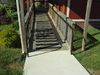
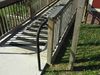
Carol Crabtree, client, is in need of a removable gate that she can attach to the end of the wheelchair ramp she currently has in place. Carol requested that the doors on the gate be able to open to a locked position or close to a lock position so that the children can run through the gate or be restricted to pass. The install and uninstall difficulty must be minimal. Finally, the gate also must be fully child proof; fully padded, no pinch points, no sharp edges, etc.
Design Specifications
- Completely removable.
- Child proof; latch accessible from outside only, fully padded, no pinch points, etc.
- Span 60 3/16" and take into account an extra inner rail.
- Height from 33" to 41".
- Must be sturdy and long lasting.
Conceptual Design
Design Concept 1
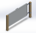
Sliding double door gate
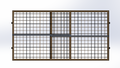
Front view
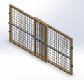
Isometric view
Pros
- Simple setup and take down, one piece
- Transportation, one piece
- Impact durability (child attempts to breakout)
Cons
- Not versatile
- Full assembly must be removed for building access
- Overall size is large
Design Concept 2
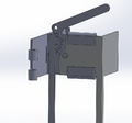
Single door with a solid hanging latch assembly

Front view
Isometric view
Pros
- Simple setup and take down, one piece
- Transportation, one piece
- Impact durability (child attempts to breakout)
- Solid latch makes setup easier
Cons
- Locking mechanism may be cumbersome
- Swinging door may be restricted by "black rail"
Design Concept 3
Double door with a solid hanging latch assembly
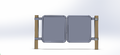
Front view
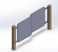
Isometric view
Double solid latching mechanism
Pros
- Solid latch makes setup easier
- Locking mechanism will be simple
- Avoids "black rail"
Cons
- 2 doors adds an extra step to setup
- Transportation may be cumbersome
- Impact durability (child attempts to breakout)
Evaluate concepts/select candidate
Detailed Design
Description of selected design
We have selected design #1 based on the Engineering Analysis done above.
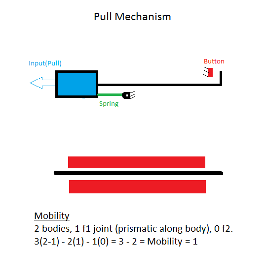
This design will utilize compression and friction force to hold the gate in a specific location with rubber bumpers. A lever will be used between two doors to apply the compression at each end of the gate. The doors of the gate will be covered in a rubber mesh to insure that children can not crawl through the gate.
Engineering analysis 1
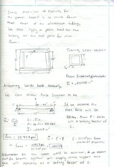
Analysis of a 100 pound point load on one beam to test rigidity and make sure tubing will be thick enough.
Result: Point load with slight plastic deformation at a safety factor of 2. Assume that multiple beams is stronger than one, then tubing will work.
Engineering analysis 2
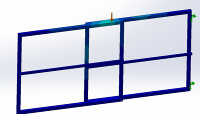
Analysis of a 50 pound child hanging from or climbing over gate.
Result: Point load with negligible deflection.
Engineering analysis 3
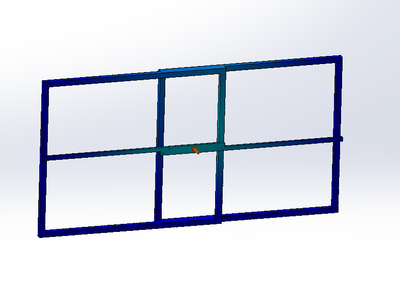
Analysis of a 50 pound load applied to the front of the gate. Simulating a 50 pound child hitting the gate.
Results: Point load with negligible deflection.
Engineering analysis 4
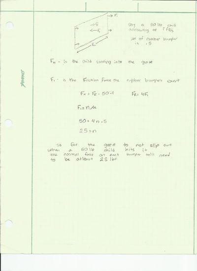
Analysis to determine the necessary friction force exerted at each bumper to hold the gate in place when a 50 pound load is applied from the front of the gate.
Results: There must be at least a 25 pound normal force on each bumper to hold the gate in place.
Weight analysis
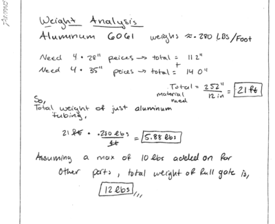
Weight analysis is of 1" x 1" with a wall thickness of 1/16" aluminum tubing. If we assume the tubing will be 90% of the weight, then this weight analysis will give a close guess. Our goal is less than 15 lbs.
Results: Total weight of both frames will weigh 6 lbs. It is safe to assume that the max weight of the gate will not exceed 12 lbs.
CAD Drawings
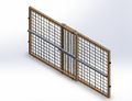
Isoview
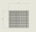
Door Dimensions
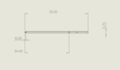
Crossbar 1
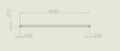
Crossbar 2
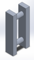
Hinge for Crossbars
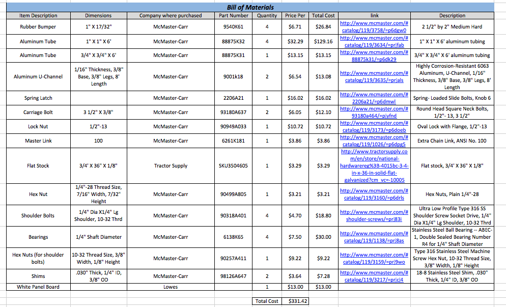
Bill of Materials
Assembly Instructions
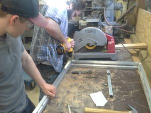
1. Cut tubing for frame and locking mechanism based on CAD drawings
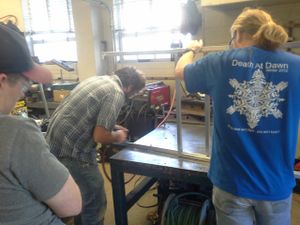
2. Weld tubing together to make frame
3. Weld C-Channel to gate frame as a guide for ball bearings
4. Drill holes for locking mechanism and for shoulder bolts
5. Attach teflon for frictionless sliding where needed
6. Bolt the locking mechanism to frame
7. Attach ball bearings and shoulder bolts to both frames
8. Cut dry erase board to size, add rounded edges
9. Glue trim to the edge of white board, for a water prove finish
10. Using rivets attach white board to gate frames
11. Clean
Fabrication Process
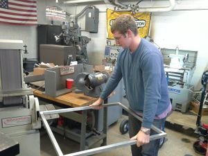
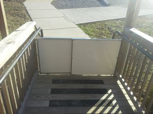
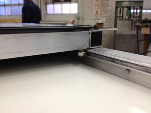
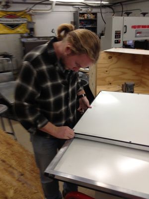
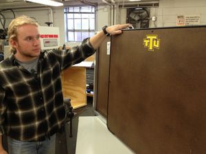
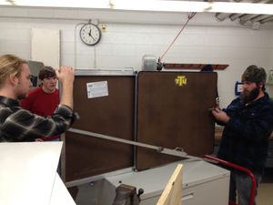

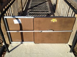
Completed design

Instructions for safe use
- Operator must be an adult or be supervised by an adult.
- When operating the mechanism, all hands must be away from the roller track.
- No climbing over the gate.
- Most of all have fun while in use.
Summary and Conclusions
The project was to design a gate to keep children from running off the end of a wheelchair ramp. The gate would need to be made out of something more durable and weather resistant than wood. Thin wall aluminum tubing was the best option to keep weight down and make the gate durable. A aluminum wire mesh was the first concept design but that proved to have some flaws (welding difficulties). The decision was made to use white board instead, not only to make the interior of the gate stronger but to also give the children a way to interact with the gate. One of the most difficult parts of the project was designing a mechanism that would all both doors to slide with ease but also have the high durable to last long. Ball bearings were used along with a small c-channel to guide the bearings back and forth along their respectively opposite gates. This allowed for not only a clean look but also keep the force required to open and close the gate to a minimum. The gate has sufficient mobility and versatility so that Carol could easily install and uninstall the gate anywhere on the ramp.
The main goal of the project was to please our customer. Through hard work by all members of the group and great team work, the group was able to supply Carol Crabtree with a product that she was thoroughly pleased with.