Zip-team 6
Abstract
The clients in our project are children between the ages of 2-5 years old with some physical limitations. The therapist contact, Renee' Canfield, wanted us to design an indoor human-powered zip line in order to give the children exercise and physical development. Mrs. Canfield wanted a zip line that would enable to children to not only use their hands but potentially their feet as well. Our goal is to deliver a zip line that will allow the children to exercise, while also helping the children develop future cycling skills.
Team members
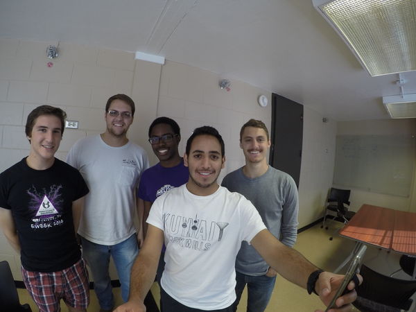
From Left to Right:
- Spencer Freeman
- Eric Umphrey
- Marsalis Pullen
- Nayef Alenezi
- Josh Martin
Special Thanks:
- Therapist = Rene Canfield
- Jeff and the mechanical engineering shop team
Problem Statement/overview of the need
This project is going to be an indoor zip line for the clients. Since the children will potentially be moving forward to trike/bicycle stage- the design of the zip line must include foot pedals, while exercising their arms with handcrank/gear system. A seated zip line with foot and hand bicycle pedals is the basic design of this project.
Design Specifications
- 1. Children ages 2-5.
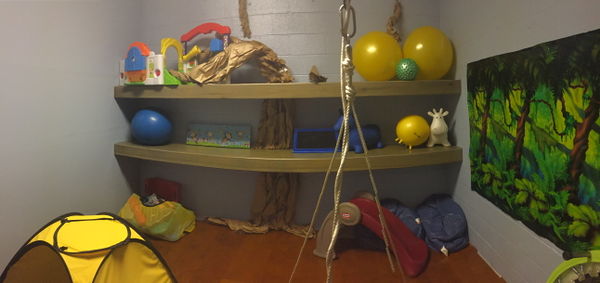
- 2. Indoor playground area ( approx 9 to 10ft wide)
- 3. Jungle Theme (Anything besides flat black)
- 4. Variation in resistance for the children
- 5. Any wire/rope/chain that can sustain every child's weight
Background research
- Basic Description of Need:
- - There are not many seated zip-lines that exist for small children
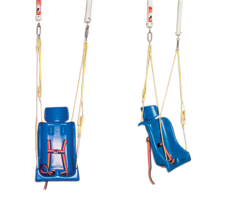
- - The only design somewhat close to our idea is the zip-line idea shown below; however, this is way to big for any of our client(s)
- Existing Ideas in the Market:
.jpg/400px-EcoFlyer_TouchCloud_(1).jpg)
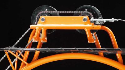
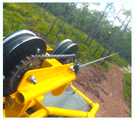
- Final Notes On research:
- We decided to utilize the same idea of the zip-line shown above in terms of body and structure.
- We didn't want the device to be like a standard child's bike, so several modifications will be made to still provide
- the fun of a zip-line and exercise of bicycle.
Conceptual Design
Summarize your conceptual design process. Develop at least three concepts.
Design Concept 1
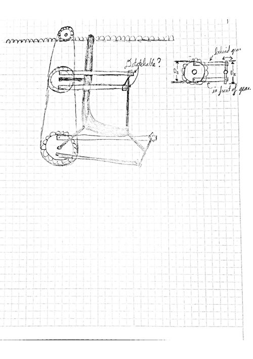
- This design incorporates two top gears in mesh with a gear train. The center of the top gears are attached with a metal beam, linking the gears together with two revolutes. The peddles have a chain connecting them to the top front gear to invoke translational motion when the peddles rotate. The seat would be fairly standard and attach to the top back gear for stablilty.
- schematics/pictures/drawings
- estimates on performance/simple calculations if needed
-page-001.jpg/500px-Doc_Sep_13%2c_2015%2c_17_05_(1)-page-001.jpg)
Design Concept 2
The idea behind this concept is to use a winch system to propel a "zip-line bike." This would allow for an adjustable length and angle in the room, depending on mounting points, and allow backwards travel.
-page-002.jpg/500px-Doc_Sep_13%2c_2015%2c_17_05_(1)-page-002.jpg)
Design Concept 3
This concept is focused on a fixed speed design that incorporates both arm and leg work to move a person. The motion can be forward or backward, depending on which way the hands and feet are rotated. The anchors for the chain/cable/gear rack are vertically adjustable such that the chair and chain/cable/gear rack can be moved out of the way. This will minimize occupied space and minimize danger from unintended contact with the chair and chain/cable/gear rack.
-page-003.jpg/500px-Doc_Sep_13%2c_2015%2c_17_05_(1)-page-003.jpg)
Design Concept 4
This concept design is an improvement on the third concept design above. Rather than have the gears and chains in front of the child as he/she sits in the seat, the gears and chains are behind the seat, and are propelled by linkages between the foot/hand shafts. The gearing system will be the same as in the third concept design.
Design Concept 5
This concept is focused on using a drum/wench mechanism with handcranks on each side to propel the child forward. This motion is limited to only one direction, so the child can only go to one side of the room and stop. In order to repeat the process, the pins in the drum/wench mechanism must be disconnected so the handcranks can remain idle as the rope unwinds. The seat is not rigidly connect to the beam through a metal bar instead there are pins in the back of the seat that can be easily pulled out to let seat disconncet from the bar. The bar is attached to the hollow beam through a pair of rollers that sit inside to allow translation and rotation.
-page-002.jpg/500px-Doc_Sep_20%2c_2015%2c_16_09_(1)-page-002.jpg)
Evaluate concepts/select candidate
- The following table is an unscientific evaluation of the designs' ability to meet the needs of the client. The ability to do so is given a rank between 1 and 5 (1 being the least favorable and 5 being the highest).
| Collapsable | Stabilitiy | Light Weight | Comfortable | Restraining | Total (Out of 25) | |
|---|---|---|---|---|---|---|
| Concept 1 | 2 | 3 | 3 | 4 | 5 | 17 |
| Concept 2 | 3 | 3 | 2 | 4 | 5 | 17 |
| Concept 3 | 1 | 5 | 1 | 3 | 5 | 15 |
| Concept 4 | 2 | 2 | 2 | 4 | 4 | 14 |
| Concept 5 | 5 | 3 | 4 | 4 | 5 | 21 |
Detailed Design
Description of selected design
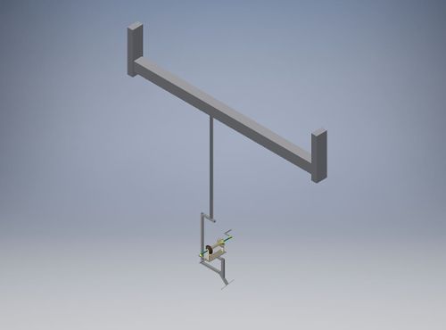
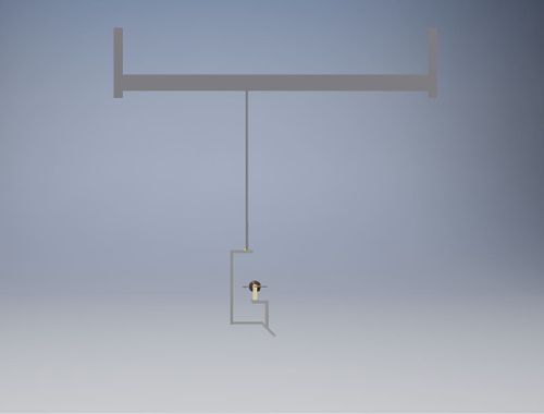
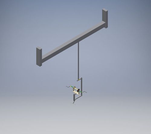
- Project Design Concept 5 is our final design choice. In this design the cable and fixed gear systems are removed. The fixed gear system is replaced with a drum/wench mechanism to allow the children to pull themselves forward by winding the rope around the drum. The cable at the top is replaced with a rolling track modeled as a fixed beam.
Detailed description of selected design
The chosen frame for the seat be made from steel plates and tubing for its weldability and strength. The frame will have a G shape to allow for more support against the weight of the child and drum. The frame will consist of adjustable foot pedals at the bottom of the frame consisting of a smaller tube inside a larger original tube to compensate for the different heights of the children. Another tubing will be placed 45 degrees near the top of the larger foot pedal tube. The frame of the drum will also consist of adjustable tubing to allow for children of varying height so their elbows can be bent at least 90 or 45 degrees. The seat is made from hard plastic that will be bolted at the bottom to the of a steel plate which will be then welded to a steel steel.The bar that will hold the seat/frame/drum to the beam will be made from square hollow steel for its malleability and strength. The bar is a rectangular hollow square tube for sliding into the smaller tube (which is situated at the top of the seat frame). Whenever these two pieces are connected, they will each have three pairs of holes in the sides to allow someone to easily remove the hitch pins as well as to keep the bodies together. At the top of the bar a thin plate at the top to connect the two guide rollers to the hollow tubing. Lastly, the beam and ceiling supports will be made from galvanized steel. The beam will have a track on the inside to allow the guide rollers to move from one side to the other. The wall supports will be bolted to the ceiling to ensure the beam is steady as the child moves across the room.
Analysis
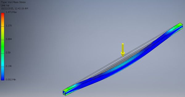
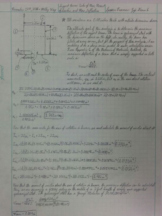
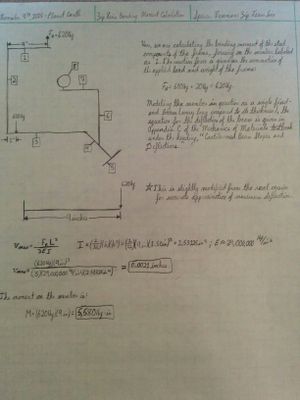
- Engineering analysis 1 was conducted in Inventor to calculate the maximum stress and deflection occurring in the beam if a maximum load of 600 pounds is added. The hand drawings include a summary of the deflection in the beam.
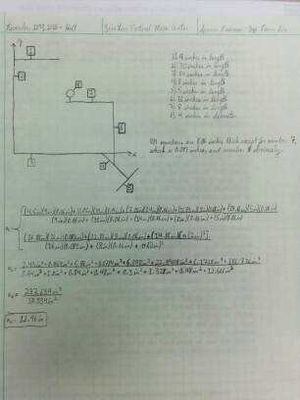
- Engineering analysis 2 was to calculate the maximum deflection occurring in the beam if a maximum load of 600 pounds is added. The force and shear stress resisted by each pin at the connection point. Also, the maximum strain occurring in the frame (modeled steel) if 600lbf is added. The center of mass is calculated as well.
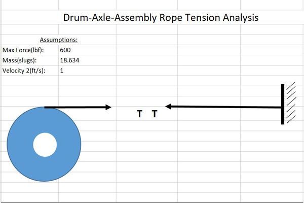
- Engineering analysis 3 was to see the maximum amount of tension that would be in the rope at an instance and to see how big of a moment would be created in the seat frame by this tension.
Engineering analysis 1
The goal of this analysis was to see how much the beam deflects as well as where the maximum stresses occur if the maximum force of 600 lbf is applied to the middle of the beam.Also, the following images are hand calculations that specifies a maximum deflection that is within the elastic range, and determines the dimensions for the design of the rigid bar.
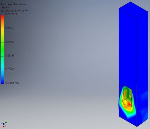
Engineering analysis 2
The goal of this analysis was to see the maximum bending moment in the frame if the maximum force of 600 lbf is applied to the middle of the seat. On the right is our calculation of the center of mass of the seat frame.
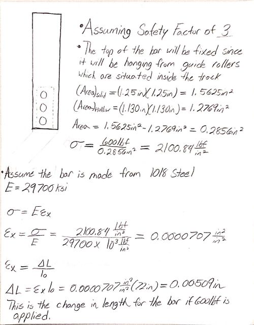
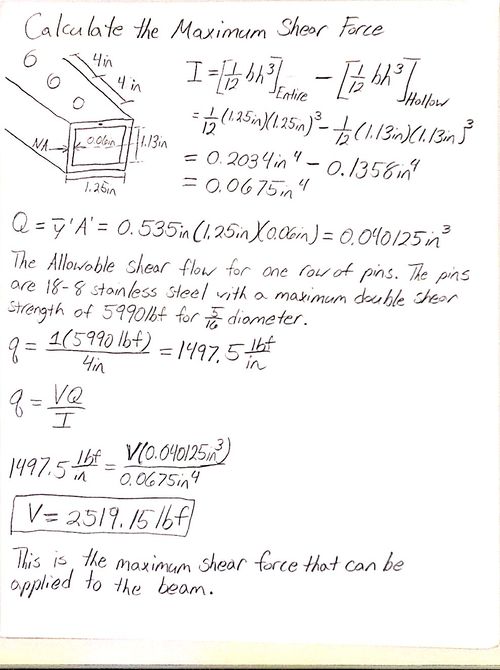
The goal of this analysis was to see how much the length of the top bar would change when a 600 lbf is applied to the middle of the seat. Also, the maximum shear force that could be applied to the beam using 5/16 diamter hitch pins to keep the frame in place.
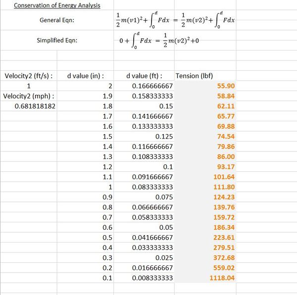
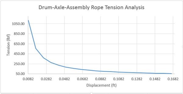
Engineering analysis 3
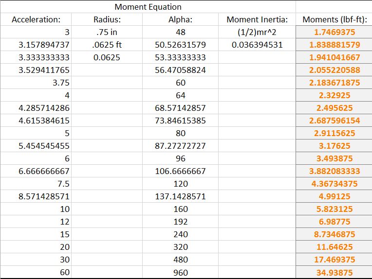
The goal of this analysis was to see the maximum amount of tension that would be in the rope at an instance and to see how big of a moment would be created by this tension. We used conservation of energy to calculate the maximum tension in the rope, then picked displacement values ranging from 2.0 in to 0.1 in. The maximum force that could be created by instantaneous velocity acting a very short distance. Next, we graphed the results of the tension calculations, and concluded as the values approached a realistic displacement the tension decreased significantly. The second set of calculations was for the moments; we started out by relating tangential acceleration to angular acceleration. Once we had the angular acceleration values we multiplied them by the constant moment of inertia for the drum assembly. The conclusion was consistent with the results of our tension calculation.
CAD Drawings
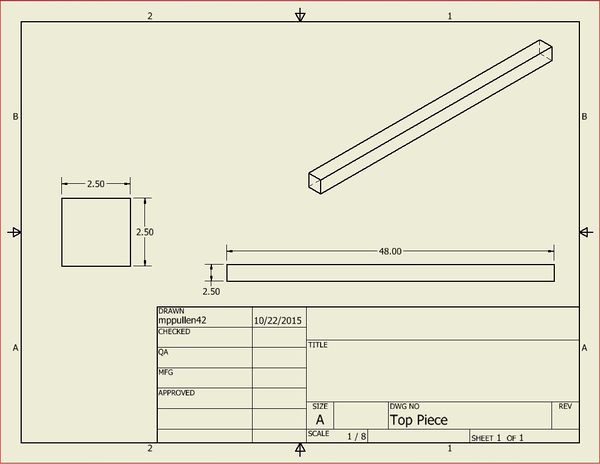
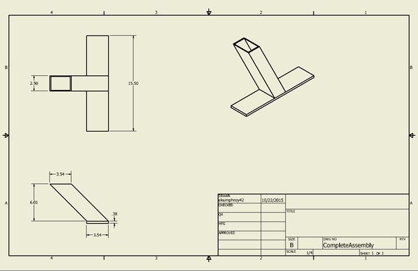
The Inventor drawing for the rigid beam is shown below.
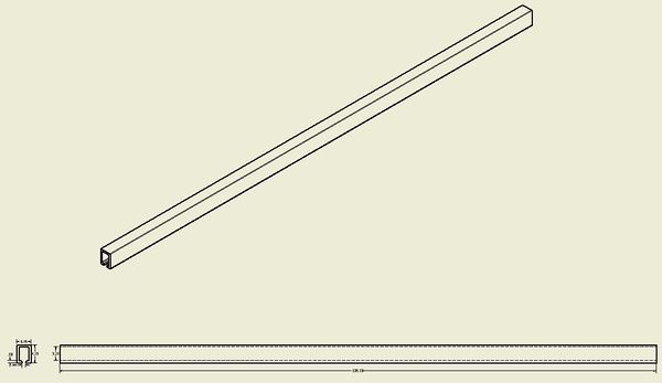
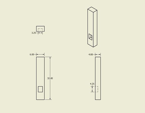
The Inventor drawing for the rigid beam support is shown below.
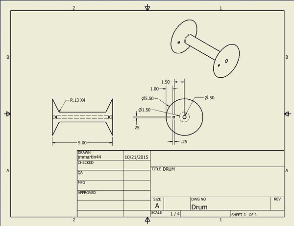
The Inventor drawing for the drum is shown below.
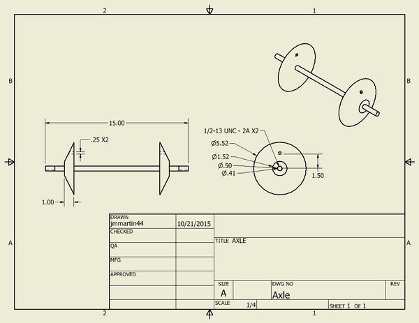
The Inventor drawing for the drum axle is shown below.
The Inventor drawing for the drum pin is shown below.
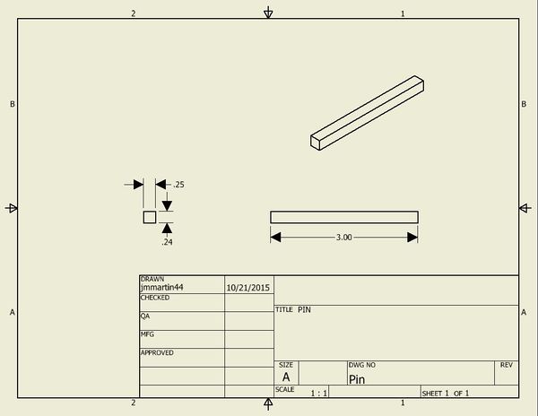
The Inventor drawing for the drum plate is shown below.
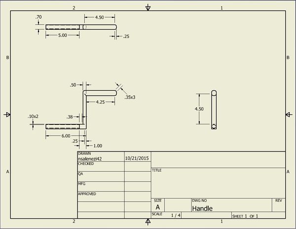
The Inventor drawing for the drum handle is shown below.
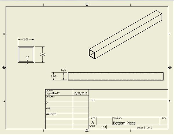
The Inventor drawing for the bottom bar is shown below.
The Inventor drawing for the top bar is shown below.
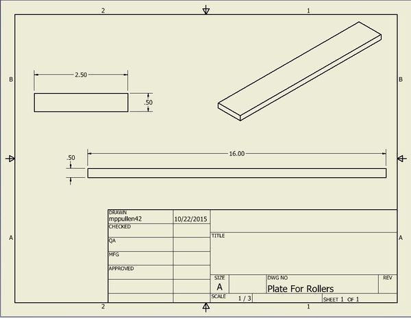
The Inventor drawing for the plate for the guide rollers is shown below.
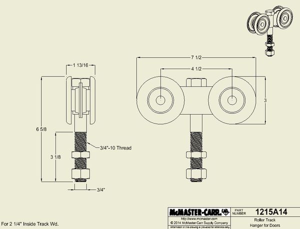
The Inventor drawing for the guide rollers is shown below.
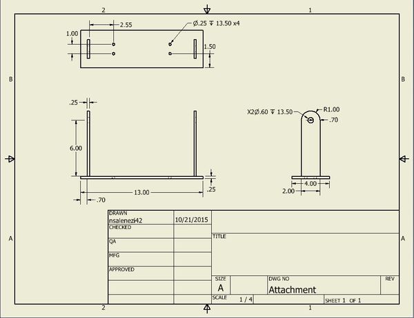
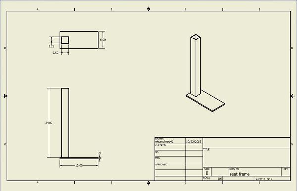
The Inventor drawing for the seat frame is shown below.
The Inventor drawing for the foot rest is shown below.
Bill of Materials
| QUANTITY | ITEM | DESCRIPTION | SOURCE | PART # | PRICE (total for each line) |
|---|---|---|---|---|---|
| 1 | Track | 12' Long, Galvanized Steel | Tractor Supply | $44.99 | |
| 1 | Guide Rollers | 600 lb./Pair Cap, Zinc-Plated Steel for InsWd : 2-1/4" | Tractor Supply | 5040 N1 -8150 | $57.99 |
| 1 | Seat Frame | 20 ' Steel Hollow Tubing 1-1/4' by 1-1/4 ' 0.06 thick | Jeff | - | $35.00 |
| 2 | Male Plate/Back Plate/ Foot Rest | Steel Sheet, 1/4" Thick, 6" x 6" | Machine Shop | - | - |
| 1 | Seat Bottom Plate | Steel Sheet, 1/4" Thick, 12" x 12" | Machine Shop | - | - |
| 1 | Seat | Full Support Swing | fab-ent | 30-1634 | $75.00 |
| 1 | Support Drum | 3' Steel Square Tube 1-1/2" Wide, 1-1/2" High, .083" Thickness | McMaster-Carr | 6527K274 | $20.18 |
| 1 | Male Ends for Footrest and Beam | 3' Steel Square Tube 1" Wide, 1" High, .083" Thickness | Strapworks.com | 6527K264 | $13.03 |
| 6 | Pins | 5/16" Diameter, 3" Usable Length | McMaster-Carr | 90146A063 | $16.32 |
| 1 | Rope | 25' High Strength, 1/4" Diameter | McMaster-Carr | 36965T21 | $36.50 |
| 2 | Bearings | Flanged Double Sealed for 1/2" Shaft Diameter, 1-1/8" OD | McMaster-Carr | 6384K361 | $21.12 |
| 2 | Pins for Drum | 3/16" Diameter, 2-1/2" Usable Length Quick Release | McMaster-Carr | 90985A108 | $49.14 |
| 1 | Bottom and Side Plate for Drum Frame | 3/8" thick 2" x 24" 6061 Aluminum Plate | McMaster-Carr | 89155K121 | $20.99 |
| 1 | Plate for Pins | 1/8" thick 1-1/2" x 24" 6061 Aluminum Plate | McMaster-Carr | 8975K581 | $3.45 |
| 1 | Main Reel | 2' Long 1/2" diameter Steel Rod | Jeff | - | $20.00 |
| 1 | Square Cranks | 1' Rectangular bar 1" x 1" 6061 Aluminum Bar | McMaster-Carr | 9008K14 | $6.34 |
| 1 | Pins for Cranks | Zinc- Plated with Cotter Pin, 5/16" Diameter, 1-1/2" Long, 1-1/4"Usable Length | McMaster-Carr | 97245A658 | $5.20 |
| 2 | Endcaps For Beam | NATIONAL HARDWARE DP5408B END CAP, GALVANIZED | Tractor Supply | 355211199 | $5.00 |
| 6 | Spray Paint | Green,Red,Yellow,Brown, Black | Walmart | - | $30.00 |
| TOTAL | $466.13 |
Assembly Instructions
- Cut the door track into desired length.
- Cut 1-1/4" x 1-1/4" steel tubing to make a seat frame and 4.5' bar to attach to door track.
- Cut holes into desired parts to make adjustable.
- Weld 1-1/4" x 1-1/4" steel tubing into a frame.
- Cut squares in the top and bottom of the seat to slide into seat frame.
- Weld plates onto seat frame to attach seat.
- Attach bearings into drum frame.
- Weld drum frame to 1-1/2" x 1-1/2" steel tube.
- Attach 1-1/2" x 1-1/2" steel tube to seat frame.
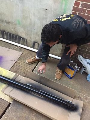
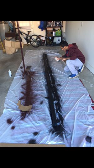
- Paint
- Test
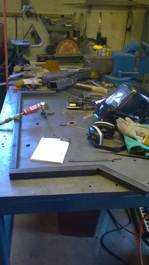
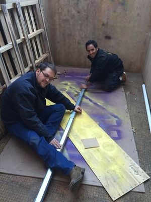
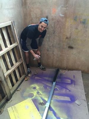
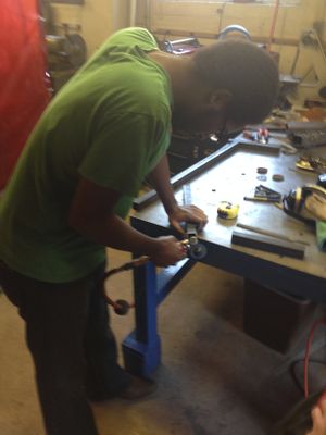
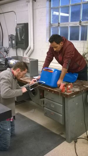
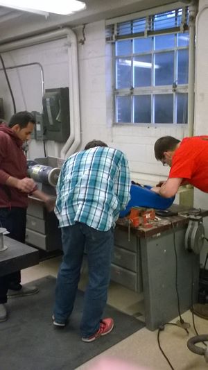
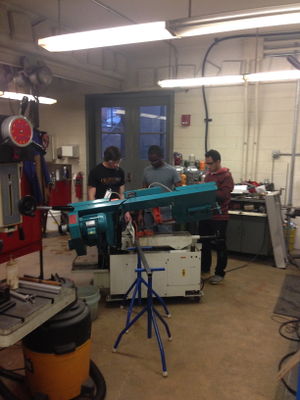
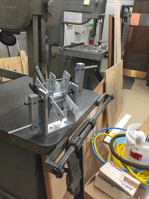
Fabrication Process
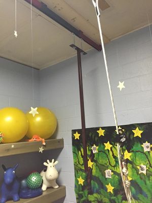
Testing and implementation
Describe testing, delivery, how used/received by the family
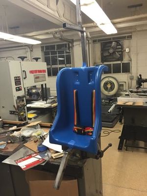
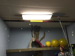
Photos of Completed design
Insert pictures of the final product
Instructions for safe use
Provide a clear summary of safe use for the family. Do not use the device unless supervised by an adult that has been fully understood the safe use of this product.