Pump-N-Go Bike
Abstract
Mrs. Draper wants a Pump-N-Go Bike as a fun way for her students to get exercise to build endurance for physical work. A back-and-forth motion with the arms will propel the bike forward. There is a nonfunctioning bike from a previous semester that we are redesigning to be safer and easier to use. [findings/outcome]
Team members
-

- Leanne Turpin, Brandon McCarter, Blake Locke, Luke Morgan, Abbey Ward
- Our point of contact for the project: Melissa Draper with the Putnam County School System.
- Our Mentor, Advisor, & Professor Dr. Stephen Canfield
- We would also like to recognize the Spring 2020 Group for their research and hard work that was ultimately cut short on this project due to COVID-19. Haden Welch, Colton Hudgens, Hayden Poirier, and Dylan Curtis
Problem Statement/overview of the need
Mrs. Draper’s high school students have varying abilities, and she needs a fun way for them to get exercise, interact with others, and learn to do physical work. Her theoretical solution was a Pump-N-Go Bike. The current design is a chain-driven, four-wheeled device that needs revamping. The current design could also use some cosmetic upgrades to make it more appealing for the students to use. The ultimate goal is to make a simple and functional mechanism for her students to use that is safe and fun for them.
Design Specifications
The bike needs to be designed to be fun, easy to operate, and easily maneuverable. This is because the students that will receive the bike have special needs, and many of them will refuse to use it if they don’t like it. The bike is also being designed to fit high schoolers ranging from 5’ 2” to 5’ 10”. The bike needs to be able to fit through doorways, so it can be ridden in hallways. As well as, the bike needs to be light for someone to pick up in case a kid gets stuck and someone needs to help them turn around. The design also needed to be focused around safety minimizing pinch points and reducing sharp edges. The bike also needs to include a lockout steering mechanism and the vehicle needs to move forward when the pump is actuated in both directions.
- Linear in Movement (Simple)
- Height Requirement: 5’2” - 5’10”
- 36” max width
Background research
1. Railway Hand Cars
- The major flaw in this concept is the lack of ability to steer the mechanism.
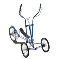
2. StreetStrider 3i (Elliptical-type bike)
- This a standing product, but we will want something sitting down
- Lean to steer
- Hand brake
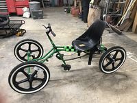
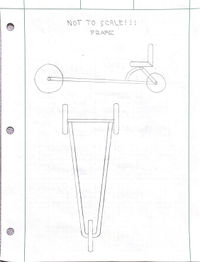
3. Previous Design
- Currently doesn’t function
- Need to get rid of chain
- Steering mechanism isn’t very good
- Size of seat is good, but it needs to be raised
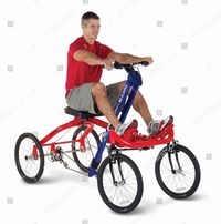
4. Rowing Bike
- In almost all models, the seat is too small
- Most are 2 wheels, but we would need more than 2 wheels
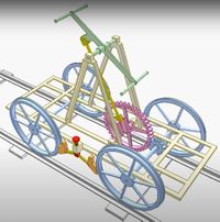
Conceptual Design
Our conceptual design is a linear motion to drive the mechanism with both feet & arms. We plan to use a link and bar system for a driveline. We plan to upgrade the current steering that exists. Our DC3 is a dolly for the teacher to use to make her life easier.
Design Concept 1
- Driveline Design 1
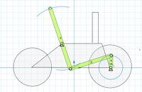
- 4-Bar Design
Design Concept 2
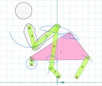
- Driveline Design 2
- 6-Bar Design
Design Concept 3
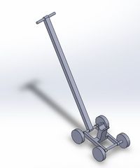
- Dolly Design for Melissa to maneuver the mechanism for the students without picking it up by hand.
Design Concept 4
- 3-Wheel Frame for Weight Reduction & Mobility
Evaluate concepts/select candidate
Our decision to use the 4-bar link system is based on simplicity, weight reduction, and ease of use.
Detailed Design
This section will describe a detailed design process
Description of selected design
We chose to move forward with a 4 wheel design. Our drive system is a 4 link design. The function will be driven by hands and feet.
Detailed description of selected design
Analysis
Describe three types of analysis to be performed on the design
Engineering analysis 1
Stress Concentration via SolidWorks
Engineering analysis 2
Weight of the bike
Engineering analysis 3
Center of Gravity
CAD Drawings
Insert drawings of all parts and the assembly
Bill of Materials
qty, item, description, source, part number, price
- 1 Dolly (Mechnical device for Mrs. Draper to use to help students navigate obstacles) [JEGS] {555-79018} $55.79
- 1 Steering Wheel Assembly (Tie-rod assembly to be used for steering mechanism) [Amazon] {GHU89001} $82.99
- 1 Pair of 2 Pedals (Standard bike pedals used to make power via foot) [Monster Scooter Parts] {X98-2542} $7.19
- 1 2pc set Foot Pedal Straps (Straps to work with pedal to secure foot) [Ebay] {174311118176} $6.57
- 1 Double Steering U-Joint (U-joint with 70 degrees of freedom to accomadate motion of steering) [Speedway Motors] {9103247} $119.99
Assembly Instructions
Fabrication Process
Insert pictures of fabrication process
Testing and implementation
Describe testing, delivery, how used/received by the family
Photos of Completed design
Insert pictures of the final product
Instructions for safe use
Provide a clear summary of safe use for the family. Do not use the device unless supervised by an adult that has been fully understood the safe use of this product.